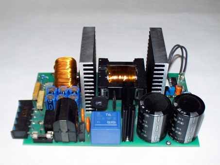
1100w smps güç kaynağı Tüm detayları ile trafo sarım formülleri güç çevrimleri ,230v filtre,mosfet hesaplamaları uc3825 pwm kontrol entegrsi hakkında bilgiler çıkış diyot hesapları dc filtre kapasite hesapları diğer komponentlerin elektronik hesapları sıcaklık çevrimleri soğutucu hesabı performans ölçümleri her şey var şema ve pcb çizimleri bulunmakta ufak bir sorun dil almanca google translate ile çeviri yapıp çözülebilir ama teknik olduğu için iyi bir çevirim sayılmaz.
Umarım almanca bilen bir okurumuz hesaplama bilgilerini Türkçe çeviri yapar bir çok kişinin gelişimine işine yarayacak kıymetli bilgiler bulunmakta
Son olarak devreyi daha denemedik fazla inceleme fırsatım olmadı ama devreyi incelediğimde geri besleme üzerinde yapılacak değişiklik ile 2×55 volt olarak çalıştırılabileceğini düşünüyorum ETD49 çıkş trafosusun sekonderi 2x olarak sarılmış doğrulma bölümünde 2 diyod yerine 4 diyod köprü yapılabilir bu konu hakkında eski bir yazım var az çok fikir verir “13-15 Volt 10 Amper Smps 30 Votl Çıkış için Modifiye”

Switching Power Supplies (SNT) to solve increasingly from conventional power supplies.
The advantages lie in the high power density, low weight and the potential Integration of protective measures such as a short-circuit protection. Especially at high Output power is the use of a SNT’s, despite the complex structure makes sense, since Construction equipment and weight compared to conventional power supplies drastically reduced will.
The required components are, thanks to modern manufacturing techniques and comparatively easy inexpensive to obtain. In this project the students deal with the development and manufacture a constant voltage source with an output voltage of 55V and an output of 1.1 kW. The supply unit will serve as a switching power supply running. It is used to power a UPS (Uninterruptible Power Supply) in the online operation. Online means here that the sinusoidal output voltage (230VRMS) constantly on the DC voltage fed inverter can be generated. The supply switching power supply must therefore the full output of the UPS facility and correspondingly powerful design be. Buffer battery, directly connected to the output of the SNT’s are connected, is Power failure the inverter will be uninterrupted energy supplies.
Mechanical requirements
• Expected mechanical dimensions of 200mm x 160mm x 95mm (lxwxh) can not exceed.
• The direction of departure of output terminals is determined.
• The position of the fan to cool the power electronics is determined.
• The mechanical criteria are defined as the power adapter into an existing housing
Electrical requirements
• The power source must be short circuit proof.
• The output voltage should UAUS DC 55V ± 2%.
• The maximum output current is 20A is IAUS.
• The minimum output current is 0.7 A. IAUS_min (Minimum input current of the inverter)
• The maximum output power is 1.1 kW PAUS.
• The efficiency should not fall below 0.9.
• The input voltage UEIN is 230V AC + 10% and – 20% at 50 – 60 Hz
• Thermal overload protection with a maximum ambient temperature of 45 ° C.
Selection
2.1 Principle of switching circuits Mains adapter
2.1.1 Single-Flyback Converter
2.1.1.1 Prinzipschaltbild Figure
2.1.1.2 Advantages
2.1.1.3 Disadvantages
2.1.2 Single-
2.1.2.1 Prinzipschaltbild Figure
2.1.2.2 Advantages
2.1.2.3 Disadvantages
2.1.3 Push-pull Durchflußwandler
2.1.3.1 Prinzipschaltbild Figure
2.1.3.2 Advantages
2.1.3.3 Disadvantages
2.2 Elected circuit
3 At ASKED THE PROJECT requirements
3.1 Mechanical requirements
3.2 Electrical requirements
3.3 anticipatory calculations
3.3.1 Input Voltage
3.3.2 Input Power
3.3.3 Input current
3.3.4 intermediate circuit voltage
Selection AND KEY DATES OF THE COMPONENTS AND 11 Heatsinks
4.1 Input fuse
4.2 Stromkompensierte Entstördrossel
4.3 Input rectifier
4.3.1 Dissipation Calculation
4.3.2 Dimensioning of the heatsink
4.4 DC bus capacitor
4.5 Inrush current limitation
4.5.1 Surge in cold NTC’s
4.5.2 Surge in hot NTC’s
4.5.3 Review of the border last integral
4.6 Interpretation of Gegentaktübertragers
4.6.1 Selection and characteristics of Übertragerkernes
4.6.2 Power Dissipation
4.6.3 Calculation of the minimum primary turns
4.6.4 Calculation of secondary windings
4.6.5 Determination of the actual ratio
4.6.6 Calculation of the maximum primary current
4.6.7 Determination of the wire cross-sections
4.6.7.1 Primary wire cross-sections
4.6.7.2 Secondary wire cross-sections
4.6.8 Determination of the copper losses of the Gegentaktübertragers
4.6.8.1 Mean Windungslängen and effective wire cross-section
4.6.8.2 copper losses of the primary winding
4.6.8.3 copper losses in the secondary winding
4.6.9 Wicklungsaufbau of the transformer
4.7 Push-pull transistors
4.7.1 Dielectric strength
4.7.2 Durchlaßverluste
4.7.3 Switching losses
4.7.3.1 losses through the output capacity of
4.7.3.2 Kommutierungsverluste
4.7.4 Total power dissipation of the push-pull switch
4.7.5 Determination of the heatsink for the push-pull switch
4.8 Dimensioning of the temperature switch
4.9 Output Rectifier
4.9.1 Minimum Blocking Voltage
4.9.2 consideration of the losses
4.9.2.1 Comparison of the data values
4.9.2.2 Calculation of Losses
4.9.3 Determination of the heatsink for the output rectifier
4:10 dimensioning of the storage choke
4.10.1 Calculation of the necessary turns
4.10.2 Calculation of the maximum Durchflutung
4.10.3 Calculation of the copper losses
4.10.4 Calculation of iron losses
4:11 sizing of transformers for voltage control production
4.11.1 Calculation of the required power control gate
4.11.2 Power consumption of the control electronics
4.11.3 dissipation of the voltage 7815
4.11.4 Required performance of the control transformers
4:12 baseload power dissipation of
4:13 Fans
5 CALCULATION OF THE TOTAL LOSS
5.1 Addition of sub losses
5.2 Calculation of the efficiency
6 POWER PROJECT DESCRIPTION AND OPERATION PLAN
6.1 SCM plan
6.2 Functional Description
6.2.1 Path of energy
6.2.2 Pulsbreitenmodulator
6.2.3 Voltage
7 Notes ON THE PWM module UC 3825
7.1 The block diagram of the UC3825
7.2 Description of functional blocks
7.2.1 Function Block 1: Error Amplifier
7.2.2 Function Block 2: PWM comparator
7.2.3 Function Block 3: Oscillator
7.2.4 Function Block 4: Or 32 Link
7.2.5 Function Block 5: Latch for PWM generation
7.2.6 Function Block 6: Toggel-Flipflop for generating the push-pull signal
7.2.7 Function Block 7: Output Drivers
7.2.8 Function Block 8: overcurrent detection
7.2.9 Function Block 9: Control of Supply
7.2.10 Function Block 10: Generation of reference voltage
7.2.11 Function Block 11: Softstarteinrichtung
7.2.12 Function Block 12: Internal auxiliary power generation
7.2.13 Function Block 13: Monitoring of the reference voltage
7.2.14 Function Block 14: Activation of the device
8 PCB DESIGN AND PLACEMENT OF COMPONENTS
8.1 Treatment of tension distances
8.2 Layout’s
8.2.1 Layout of the Components page
8.2.2 Layout of the solder
8.3 BOM and assembly Prints
8.3.1 BOM
8.3.2 Assembling the mounting pressure Page
8.3.3 solder mounting pressure from the
9 INSTALLATION
9.1 Listing of the used instrumentation and tools
9.2 Commissioning measurements
9.2.1 Review of control signals
9.2.2 Investigation of the output voltage at idle and under nominal
9.2.2.1 Height of the output voltage
9.2.2.2 Output ripple
9.2.2.3 Structure of the output when you turn
9.2.3 Recording of the currents and voltages to the push-pull switches
9.2.4 Measurement of the output current of the input rectifier
9.2.5 Recording performance and efficiency of the power supply
9.2.5.1 Measuring the Power
9.2.5.2 Review of the efficiency
9.3 Thermo Graphic recording nominal
9.4 Lessons learned
10.1 Bibliography
10.2 List of Figures
55v 20a 1.1kw smps Entwicklung eines 1,1 kW-Schaltnetzteils zur Versorgung einer unterbrechungsfreien Stromversorgung alternatif;
Şifre-Pass: 320volt.com
Yayım tarihi: 2009/04/16 Etiketler: 1kw smps, 20 amper smps, 55volt smps, etd49, pwm kontrol, schaltnetzteils stromlaufplan, stromversorgung, uc3825

merhaba gevv link de bir problem var galiba rapid dosya hatası veriyor eğer sende yedeği varsa eklermisin bana buna benzer bir devre lazım.
yapmak istediğim 0 ile 20Amper arası ayarlı DC güç kaynağı gerekiyor yanlız çıkışa kısa kabloları takıp ısınma testi yapacağım ve günlerce çalışacak bu nedenle çıkış kısa devre koruması olmaması gerekiyor genelde güçkaynaklarında çıkış koruması olması nedeniyle voltaj hemen sıfıra iniyor bu nendele işime yaramıyorlar.Güç korumalarını iptal edincede genelde ya çıkış mosfetleri yada sürücü transistörler yanıyor.
Merhaba @45mehmet alternatif rapidshare linki çalışıyor kontrol ettim iyi çalışmalar
ek olarak bir alternatif link daha 😉 http://www.4shared.com/file/139916421/a5b52b0f/uc3825-etd49-smps.html
merhaba gevv hocam ilgin için teşekkür ederim linki az önce açamamıştım şimdi kopyaladım teşekkür ederim.
@45mehmet
kardeş benimde senin gibi sağlam bir devreye ihtiyacım var kısa devre edince sürücüleri yanmayan cinsten harcadığım igbt lerin ve mosfetlerin hesabı yok bir kaç saniye dayansada uyar ve denemelerinizin sonuçlarını paylaşırsanız sevinirim
Çalıştıran varmı mosfetler patladı
ETD49’un sarım bilgilerini bulamadım. Nasıl sarılacak bu trafo?
pdf dosyasında sayfa 17, 18, 19
ben aynı trafo kullanarak irfp460 lar ile push pull devresi yapmıştım
sg3525 kullanmıştım
Pr.45 tur Se.15 turdu araya direnç koymadığım halde mosfetlerin arasına aldığım voltaç 140v maximum aldığım güçtü transistörlerde ısınma oluşu (boştayken) devreyi test etmedim ve bir şekle sokayım derken entekrenin girişlerini ters yapmışım sonuç tekral hazırlıyorum bittiğinde paylaşırım
birde bu transistörleri IXFX26N90 burada bulabilirmiyiz bana zor gibi geliyor