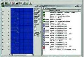
Yine epe magazine dergisinin bedava olarak dağıttığı bir proje aslında bir önceki yazıya eklenebilirdi fakat ayrı tutmak istedim çünki çok değişik bir devre dijital lojik entegreleri bu devre ile test edebiliyorsunuz bilgisayarınıza kuracağınız program ile görsel olarak test edilen entegrenin verileri görülebiliyor
Devre pic16f877 üzerine kurulu bilgisayar haberleşmesi max232 ile rs232 portundan sağlanmış bağlantı için kullanılan zif soket sayesinde farklı boyutlarda entegreler test edilebilir kaynak asm ve hex yazılımı bulunuyor test aşamaları devre çalışma prensibi ve diğer detaylar açıklanmış (ingilizce) ayrıca bağlantı kablo şamasıda bulunuyor


Assembly yazılımı
;   File: ICTesterV21.ASM
;    PIC: 16F877 @ 20Mhz
;   Date: 3-May-2002
; Author: Joe Farr
;
; Description:
; PIC software for the TTL IC tester
; 19200 Baud, No parity, 1 Stop bit @ 20Mhz XTAL
; TX from PIC on C6 (From PIC to P.C.) via MAX232
; RX back to pic on C7 (From P.C. to PIC) via MAX232
;
; Revision History
; V1.0          Initial version
; V2.0          Updated to support 24 Pin packages
; V2.1          Supports multiple RS232 speeds
;		New commands '5' and '6' added
;
; Command summary and description
; Command Byte + Optional 4 bytes consisting of 32 bits
; Commands:
; 0     Reset PIC (IC test power Off) (C0) High
; 1     IC test power - ON (C1), (C0) Low (Device no longer ready, now busy)
; 2     Set device I/O configuration (0 - Output, 1 - Input)
; 3     Set output bit pattern (0 - Low, 1 - High)
; 4     Read back result bytes (4 bytes returned)
; 5     Contin. dump logic levels
; 6     Return firmware version number
;
; Any other command causes the error indicator to be set on the device. (C2)
;
; PIC PIN Allocation and usage.
;
; PORT  IC PIN           IC PIN PORT
;-----------------------------------
;
; B7     1         	  24    E0
; B6     2         	  23  	E1
; B5     3         	  22    E2
; B4     4         	  21    A0
; B3     5         	  20    A1
; B2     6         	  19    A2
; B1     7         	  18    A3
; B0     8         	  17    A5 (NOT A4 which is open drain output and not used!!)
; D7     9                16    D0
; D6     10               15    D1
; D5     11               14    D2
; D4     12               13    D3

;
; A4 - N/U
; C0 - Baud Select jumper
; C1 - Output format select jumper
; C2 - Error In Communications/Unknown Command LED
; C3 - +5v Test IC supply to transistor and LED
; C4 - N/U
; C5 - N/U
; C6 - RS232 from PIC to MAX232
; C7 - RS232 from MAX232 to PIC

; Jumper Table
; JP1 - Baud rate
; Out - Default 19.2K
; In  - High Speed - 57.6K

; JP2 - Output format
; Out - Default - Returns ASCII codes (0 to 255)
; In  - Readable format (returns binary notation) - WILL NOT WORK WITH PC SOFTWARE

	LIST p=16f877,c=140
        errorlevel 1,-(305)
        include "p16f877.inc"

Bank0   equ     0x00
Bank1   equ     0x01
LOOP    equ     0x24
TEMP    equ     0x25
VALUE   equ     0x26
COUNT   equ     0x27
Byte0  	equ     0x70
Byte1  	equ     0x71
Byte2  	equ     0x72
Byte3   equ     0x73
Boot    equ     0x28    	; Is this the first time

	org 	0
        clrf 	STATUS
        clrf    Boot
        goto 	BootStart
        org 	4
ISR     goto 	5            	; Setup Interupt Address
	org 	5


BootStart
        ;
        ; Configure the I/O ports
        ;
        clrf    STATUS
        movlw   b'00000000'
        movwf   PORTA
        movlw   b'00000000'
        movwf   PORTB
        movlw   b'01000000'
        movwf   PORTC
        movlw   b'00000000'
        movwf   PORTD
        movlw   b'00000000'
        movwf   PORTE

        banksel TRISA           ; Selects Bank 1
        movlw 	b'11111111'     ; All inputs
        movwf   TRISA
        movlw   b'00000110'
        movwf   ADCON1          ; PortA inputs are digital not analog

        movlw   b'11111111'     ; All inputs
        movwf   TRISB
        movlw   b'10000000'     ; Disable PORTB week pullup resistors
        movwf   OPTION_REG

        movlw   b'11000011'     ; set RC0 as input for Baud rate
				; set RC1 as input for display mode select
				; set RC2 - RC5 as outputs for LED's
                                ; set RC6 - RC7 as inputs(serial)
        movwf   TRISC

        movlw   b'11111111'     ; All inputs
        movwf   TRISD

        movlw   b'11100000'     ; All outputs (only a 3 bit port)
        movwf   TRISE

;
; Read in the Baud rate Jumper setting
;
	banksel PORTC

        movlw   d'64'           ; 19.2K Baud with 20MHz XTAL
	btfss   PORTC, 0        ; Skip next if JP1 is NOT in place
        movlw   d'20'           ; Override with 57.6K Baud with 20MHz XTAL

        banksel TRISA           ; Selects Bank 1


;
; Configure the baud rate generator
;
        movwf   SPBRG           ; In bank 1
        movlw   b'00100100'     ; BRGH = 1(High speed) & ASYNC transmission
        movwf   TXSTA           ; In bank 1
        banksel RCSTA           ; Select Bank 0
        movlw   b'10010000'     ; ASYNC reception
        movwf   RCSTA           ; In bank 0
        movf    RCREG,W         ; Flush the RX buffer in bank 0
        movf    RCREG,W
	movf    RCREG,W

;
; Main start
;
        ; If this is the first time through
        ; then make sure that the Error LED is on
	; so we know the CPU is running
        ; else, switch it off since this is a reset operation.
        btfsc   Boot, 0
        goto    ResumeBoot
        bsf     PORTC, 2        ; Error in comms (LED ON)
        goto    ResumeFirstBoot

ResumeBoot
        bcf     PORTC, 2        ; Error in comms (LED OFF)

ResumeFirstBoot
	bsf     PORTC, 3        ; IC +v OFF

        movlw   mReady          ; MSG - Ready
	call    SendMessage
	bsf    	Boot, 0      	; No longer in first boot pass

WaitCom
        call 	FlushRXBuffer
        call    RecLoop         ; Wait and read from RS232 - character returned in 'w'

; Byte received
	bcf     PORTC, 2        ; Error in comms/command LED off

; Check for a command
	movwf   TEMP            ; Save 'W' in TEMP

        sublw   0x36
	btfsc   STATUS, Z       ; Check if ASCII = 54 '6'
        goto 	CmdVersion      ; Command 6 - Get version details

        movf    TEMP, W         ; Recover original value
        sublw   0x35
	btfsc   STATUS, Z       ; Check if ASCII = 53 '5'
        goto 	ContRead        ; Command 5 - Contin. dump of status

        movf    TEMP, W         ; Recover original value
	sublw   0x34
	btfss   STATUS, Z       ; Check if ASCII = 52 '4'
        goto    NxtCmd1
	call 	Cmd4            ; Command 4 - (Read back I/O values)
        goto    ConfirmCmd

NxtCmd1
        movf    TEMP, W         ; Recover original value
        sublw   0x33
	btfsc   STATUS, Z       ; Check if ASCII = 51 '3'
        goto 	Cmd3        	; Command 3 - (Set output pattern)

        movf    TEMP, W         ; Recover original value
        sublw   0x32
        btfsc   STATUS, Z       ; Check if ASCII = 50 '2'
        goto 	Cmd2        	; Command 2 - (Set I/O Configuration)

        movf	TEMP, W         ; Recover original value
        sublw   0x31
        btfsc   STATUS, Z       ; Check if ASCII = 49 '1'
        goto 	Cmd1            ; Command 1 - (IC Test Power)

        movf    TEMP, W         ; Recover original value
        sublw   0x30
	btfsc   STATUS, Z       ; Check if ASCII = 48 '0'
        goto 	BootStart       ; Command 0 - Reset detected


;
; Unknown command
;
        bsf     PORTC, 2        ; Error/CommsError LED ON

        movlw   mError          ; MSG - Error!
	call    SendMessage
	goto 	WaitCom        	; Done - Wait for next incomming data


CmdVersion
; Return the program version details
        movlw   mProduct
        call    SendMessage
        movlw   mVersion
        call 	SendMessage
        goto    WaitCom         ; Done - Wait for next incomming data

Cmd1
; Switch ON IC test power
        bcf     PORTC, 3
        goto 	ConfirmCmd

Cmd2
; Set I/O configuration by updating the TRIS values
	call    RecLoop         ; Read 1st byte - (B)
        movwf   Byte0           ; Store byte in global register
        call    RecLoop         ; Read 2nd byte - (D)
        movwf   Byte1           ; Store byte in global register
        call    RecLoop         ; Read 3rd byte - (A)
        movwf   Byte2           ; Store byte in global register
        call 	RecLoop         ; Read 4th byte - (E)
        movwf   Byte3
        bcf     Byte3, 4        ; Update TRISE - make sure that PORTD stays in general I/O mode

        banksel TRISB

	movf    Byte0 + 0x80, W
        movwf   TRISB
        movf    Byte1 + 0x80, W
        movwf   TRISD
        movf    Byte2 + 0x80, W
	movwf   TRISA
        movf    Byte3 + 0x80, W
	movwf   TRISE

        banksel PORTA

        goto 	ConfirmCmd


Cmd3
; Set test output pattern
        call    RecLoop         ; Read 1st byte
        movwf   PORTB

        call    RecLoop         ; Read 2nd byte
        movwf   PORTD

        call    RecLoop         ; Read 3rd byte
        movwf   PORTA

        call    RecLoop         ; Read 4th byte
        movwf   PORTE

	goto 	ConfirmCmd


Cmd4
; Read back I/O values
	movf    PORTB, W        ; Send 1st byte
        movwf   VALUE
        call    TxSend

        movf    PORTD, W        ; Send 2nd byte
        movwf   VALUE
	call    TxSend

        movf    PORTA, W        ; Send 3rd byte
        movwf   VALUE
	call    TxSend

        movf    PORTE, W        ; Send 4th byte
        movwf   VALUE
	call    TxSend

        return

ContRead
; Keep reading the PORT values and sending the results back
; untill a byte is received from the PC
        nop
        call    FlushRXBuffer
        call    Cmd4            ; Dump the values of the IC PINs
        btfss   PIR1,RCIF       ; Check for any RX'd data
        goto 	ContRead   	; Nothing RX'd - Do again
; Were done processing
        bsf     PORTC, 2        ; Error/CommsError LED ON - Indicates that the ContRead has been completed
        bsf     PORTC, 3        ; +5v OFF (It may or may not actually be on right now)


ConfirmCmd
        movlw   mOK            	; MSG - OK.
	call    SendMessage
        call    FlushRXBuffer
	goto 	WaitCom        	; Done - Wait for next incomming data


;
; Receive a character from RS232
; (This routine does not return until a character has been received)
;
RecLoop
        nop
        btfss   PIR1,RCIF       ; Check for any RX'd data
        goto 	RecLoop         ; Nothing RX'd
        movf    RCREG,W         ; Store the RX'd data
        return

;
; Decide what to send back to the PC
; Single bytes (which are faster) or Binary strings (which are east to read)
;

TxSend
        btfsc   PORTC, 1
        goto    TxByte          ; Jumper 2 Missing (Default)
        movf    W, VALUE
	goto    TxBinary        ; Jumper 2 Inserted
;
; Send a byte to the USART
;
TxByte
        nop
        btfss   PIR1,TXIF       ; TX buffer empty ?
        goto    TxByte          ; No - Keep waiting

        movwf   TXREG           ; TX Buffer empty - send the character
        return

FlushRXBuffer
	movf    RCREG,W        	; Flush the RX buffer in bank 0
        movf    RCREG,W
	movf    RCREG,W
        return

;
; Send contents of 'VALUE' to Serial as 8-bit binary
;
TxBinary
	movlw   mCRLF          	; MSG - CRLF
	call    SendMessage
	movlw   0x08            ; Process 8 bits (0-7)
        movwf   COUNT

NextBit
	movlw   0x31            ; '1'
        btfss   VALUE, 7        ; Test bit 7
	movlw   0x30            ; '0'

        call	TxByte          ; Send ASCII code for bit
	rlf     VALUE, F        ; Rotate left through carry
        decfsz  COUNT, F        ; Decrement bit position counter
        goto    NextBit         ; Process next bit

        movlw   mCRLF          	; MSG - CRLF
	call    SendMessage
        return


;
; Send the specified message to the serial device
;
SendMessage
        movwf	LOOP            ; Set the OFFSET of the table
SendMes2
        movf    LOOP, W         ; Load pointer to character
        call    MsgTable        ; Returns with 'W' = ASCII char to send or ASCII 0 = EOM
        movwf   TEMP            ; Save returned ASCII character
        ; Test for EOM
        sublw   0x00

	btfsc   STATUS, Z    	; EOM character found
        return                  ; Yes

        movf    TEMP, W         ; Recover original value
	call    TxByte          ; Send character to serial port
        incf    LOOP, F         ; Point to next character in msg
        goto    SendMes2        ; Not done yet


;*******************************


;
; Setup message table
;
MsgTable
mError	equ     0x00
        addwf   PCL, F
        retlw   'E'             ; Error
        retlw   'r'
        retlw   'r'
        retlw   'o'
        retlw   'r'
        retlw   '!'
	retlw   d'13'
        retlw   d'10'
        retlw   d'0'            ; EOM

mOK   	equ     0x09
        retlw   'O'             ; OK
        retlw   'K'
        retlw   '.'
        retlw   d'13'
        retlw   d'10'
        retlw   d'0'            ; EOM

mReady  equ     0x0F
        retlw   'R'             ; Ready
        retlw   'e'
        retlw   'a'
        retlw   'd'
        retlw   'y'
        retlw   '.'
        retlw   d'13'
        retlw   d'10'
        retlw   d'0'            ; EOM

mCRLF   equ     0x18            ; CRLF
        retlw   d'13'
        retlw   d'10'
        retlw   d'0'            ; EOM

mProduct equ    0x1B            ; Product description
        retlw   'D'
        retlw   'i'
        retlw   'g'
        retlw   'i'
        retlw   't'
        retlw   'a'
        retlw   'l'
        retlw   ' '
        retlw   'I'
        retlw   'C'
        retlw   ' '
        retlw   'T'
	retlw   'e'
        retlw   's'
        retlw   't'
        retlw   'e'
        retlw   'r'
        retlw   d'13'
        retlw   d'10'
        retlw   d'0'            ; EOM

mVersion equ    0x2F            ; Version number
        retlw   '2'
        retlw   '.'
        retlw   '1'
        retlw   '/'
        retlw   '0'
        retlw   '1'
        retlw   '.'
        retlw   d'13'
        retlw   d'10'
        retlw   d'0'            ; EOM

        end
IC Tester;
bilgisayar-baglantili-dijital-lojik-entegre-test-devresi ZIP Dosyası Şifre-Pass: 320volt.com


ben protobord üzerine yapmıştım bir devre ama pek kullanışlı olmadı.Bunu deneyecem çok iyi bişeye benziyor -zaten PIC le yapılan her şey çok iyi oluyor.paylaşım için teşekkürler
İşe yarayacak güzel bir devre. teşekkürler.
Kardeşler ben bu rar dosyayı indiremedim dosya hasarlı hatası veriyor. Bir yardımcı olsanızda inceleyip fikir söylesek bizlerde
teşekkür ederim. bununla ilgili bir sorum var. VI test cihazı hakkında bilginiz varmı??? Devre şeması bulabilirmiyiz?
Hocam ben bu devreyi yaptım ama bir türlü çalıştıramadım.
Yazılımsal bir sorun olduğunu düşünüyorum. Asm dosyasını Hex’e çevir dediğimde hatalar alıyorum. Kafayı taktım ama olmadı ne olacak şimdi bilmiyorum.
Asm dosyasını Hex’e çevirebilecek olan varmı acaba?