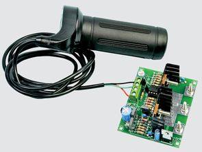
The power of the DC Motor speed control circuit can work between 30 amps and 12…32 volts. Speed control is done with PWM technique. It has “Reversible” reverse, straight control feature. Circuit LM358, CD4093, and IRF2804 speed control based on mosfets can be made with a 5k potentiometer or a joystick called “hall effect throttle”.
12-32V 30A motor speed control soft start circuit, relay switching motor direction PWM speed control circuit
30A Motor Speed Control Circuit

According to the DC Motor Speed Controller High Power, materials that are easy to build can be found between 12-32V and 30A . It features soft start, relay switching of motor direction and PWM speed control.
The DC Motor Speed Controller uses a pair of high power Mosfets connected in parallel to drive the motor and relay circuitry to make the motor reversible. It can operate from 12-32V batteries at currents up to 30A. The logic control of the reversing circuit means that it can only change direction when the motor is stopped.
The unit consists of two parts. The first is basic speed control with two parallel Mosfets and a dual op amplifier to provide pulse width modulation (PWM). The second section adds the relay circuit and logic control. If you don’t need motor direction reversal, you can just do the PWM control stage of the circuit

Speed control can be achieved via a built-in trimpot, an external 5k potentiometer, or a motorcycle throttle based on a Hall Effect sensor. This could be ideal for a wheelchair controller or electric bike.
Motor Speed Control Oscilloscope Images
Figure 1: Shows the basic control operation. The triangle wave from the oscillator is compared to a 3.5V reference (pink line) and when it exceeds this reference, a corresponding motor driver pulse (blue line) is produced.

Figure 2: Shows operation at higher speed settings. The triangular waveform now exceeds the reference voltage for a greater portion of the time and therefore the pulses fed to the motor are much wider.

Circuit description
First, let’s focus on the IC1 (LM358 dual op amp) and the 5k potentiometer. The op amp IC1a and its associated components include a triangle wave oscillator. Its frequency is around 300Hz and output amplitude is around 1V peak to peak. The average DC level of this triangular waveform can be raised or lowered depending on the setting of the 5k speed control potentiometer.
This output waveform is connected to the non-inverting input of IC1b, pin 5. IC1b is connected as a comparator and compares the triangular waveform with the 3.5V fixed reference on pin 6. The triangular waveform on pin 5 exceeds the 3.5V reference voltage on pin 6, the output on pin 7 will go high and this will turn on the two power Mosfets (IRF2804), Q6 and Q7.

This means the Mosfets are pulsing when the triangular waveform peaks above 3.5V. Advancing speed control increases the duty cycle of the pulses.
Circuit operation is illustrated in the Oscilloscope measurements in Figure 1 and Figure 2. In all cases, the green line indicates the triangular waveform, while the pink line indicates the 3.5V reference, which is stable. As you can see, every time a part of the triangular waveform intersects with and is above the pink line, there is a pulse to the Mosfet gates as shown in the blue line. The voltage across the motor between the positive supply line and the Mosfet drains is indicated by the yellow line.
Source: http://www.siliconchip.com.au/cms/A_112070/article.html 30A Motor Speed PWM Control schematic pcb files Alternative link:
FILE DOWNLOAD LINK LIST (in TXT format): LINKS-13320.zip pass: 320volt.com
Published: 2010/11/29 Tags: motor control circuit, motor driver circuit, pwm circuits
3 Bit Counter Circuit TTL 7447 74160 NE555
74160 7447 3 bit counter designed with integrated tll. For each bit, 1 display, to drive displace 74,160 in 7447 and counting is used. 74 160 s 3-bit counter formed by connecting serial number of 74160 can be increased by increasing the number of bits.
Circuit NE555 square wave oscillator circuit to provide clock pulses and 50 Hz oscillator source used with the 4052. By pressing the START button 555 out of outputs HIGH level for a certain time. X1 output from 555 in 4052 to the “1” with the knowledge of the information in 50hz oscillator to give a total. X1 by taking exit 50 Hz signal that will be applied on the circuit in the output circuit 555 is “0” will continue until the counting.
I require a simple circuit to interconnect 24v x 250w PMDC Motor, 24 volt Battery and Padel Assist Sensor
https://320volt.com/en/yuksek-guclu-30-amper-dc-motor-hiz-kontrol-devresi/ tested works great.
If you don’t have a 358, with a Darlington on the input, you can use two 741s, or a dual 4558 with a few minor modifications.
https://ibb.co/H43vVw9
Hi, Thanks for informations.
🙂