Jeff Bagby and Charlie Out great things with Excel, very detailed, active, passive crossover and woofer had prepared programs
Passive Crossover Designer
Excel application for designing passive crossovers and equalization The purpose of the this spreadsheet is to allow the user to accurately simulate the frequency, phase, and impedance of a two or three way speaker with crossover using imported data files of the actual measured responses. The data file types used correspond to Liberty Instruments “Imp” and “Audiosuite” frd type frequency response data, and zma /zda impedance data files. Sample data files have been included with this spreadsheet to allow the user to experiment and gain a better working knowledge of the program.

I have included woofer, midrange, and tweeter frd and zma files, as well as standard 90 dB, 8 ohm, and 4 ohm files. The latter group are useful for simulating textbook crossover types. Explanation of these files and their use is covered at the bottom of the User Guide.
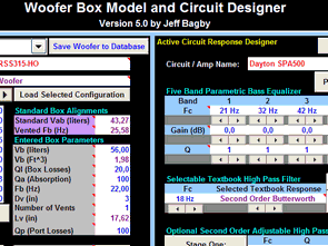
Woofer Box and Circuit Designer – The most accurate Sealed, Vented, and Passive Radiator modeling tool available – Complete with amplifier modeling and the ability to include room and baffle effects in the response
Active Crossover Designer
(ACD) – A set of tools for designing active loudspeaker crossovers using a series of linked Excel spreadsheets. Complete control of transfer function using pole and zero notation. Generates “advanced biquad” coefficients for the MiniDSP crossovers. Core tools are extensible via extensions.
source: audio.claub.net/software.html alternative link:
FILE DOWNLOAD LINK LIST (in TXT format): LINKS-25410.zip
Published: 2016/04/21 Tags: electronics software tools
Electronic Circuit Diagrams Part-1
9 seconds display timer circuit
Display timer display circuit “””timing circuit NE555 CD4017 LED indicator 9 seconds” counter cd4511 CMOS circuit for the display relay output circuit BDC has developed a bit more again added the devices that connect to the relay contacts can be controlled.
Tiefton Frequenzweiche Fach-Entwurfs-Programmen
Jeff Bagby und Charlie Sich große Dinge mit Excel, sehr detaillierte, aktive, passive Frequenzweiche und Tieftöner vorbereitet hatten-Programme