There are two ds 1621 thermometer circuits without using a microcontroller, as well as the program and source codes prepared with Visual Basic 5, the program saves the data as a text file, and the circuit communicates with the computer via the rs232 port.
DS1621 thermometer
It does not use any programmable components as a microcontroller. It gives accurate temperature readings down to 0.5°C without the need for calibration. It’s cheap, so I put one in any PC I use. And the display of the temperature in the Windows taskbar is so nice that a million friends 🙂 asked me to make one!
Since I don’t have time to create a million pcTHERM, I am giving you the plans and software to create one yourself. This project is easy enough for beginners, the only difficulty is probably due to PC-to-PC serial port hardware incompatibility. In the single-sensor version, you only need the sensor IC, a voltage regulator, and a handful of diodes and resistors.
Build and learn the secrets of the IIC bus, how to implement the IIC bus using just two resistors and a few zeners, drive it on a serial port using Visual Basic. Relevant components are available in the worldwide catalog of RS components.
DS1621 pc thermometer
Contents
So cool you can even measure it!
This incredibly simple thermometer plugs on any free serial port. Does not make use of any programmable components as microcontrollers. It gives temperature readings accurate to 0.5°C with no calibration. It’s cheap, so I’ve put one on any PC I use. And it is so nice to have the temperature shown on the Windows taskbar, that a million friends asked me to build one!
Build yourself an accurate thermometer
Since I have no time to build a million pcTHERMs, I give you the plans and the software to build one on your own. This project is easy enough for beginners, the only difficulties possibly arising from serial port hardware incompatibility from PC to PC. In the single-sensor version, you need only the sensor IC, a voltage regulator and and handful of diodes and resistors. Build it, and learn the secrets of IIC bus, how to implement IIC bus using only two resistors and a couple of zeners, how to drive it on a serial port using Visual Basic .Components involved are available on the worldwide RS-components catalogue.
PC Thermometer features
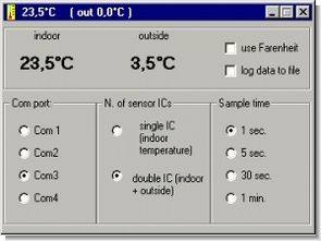
displays both indoor and outside temperature on the Windows taskbar (see figure)
plugs in any free PC com port
range -20 … +125°C (-4 … 257°F)
basic accuracy and resolution 0.5°C
Centigrade (°C) of Farenheit (°F) scale
data logging on easily readable text file
sampling rate 1, 5, 30 or 60 seconds
one or two temperature sensors (upgradeable up to 8)
com port powered, no external power supply required
easy to build, no exotic nor programmable parts inside
no calibration required
full source code available for free (educational and non-commercial uses only)
DS1621 Thermometer Circuit Schematic

Parts list
2 x 1N4148 diodes
2 x 5.1 volt 1/4W zeners
2 x 4700 ohm resistors
2 x 100 nFcapacitors
2 x 47uF 16V el.capacitors
2 x DS1621 digital temperature sensors (Dallas Semiconductor)
1 x LM2936-z5 low-droput 5V regulator(National Semiconductor)
1 x DB9 female plug.
How it works
The circuit is derived from the Claudio Lanconelli’s PONYPROG programmer (I recommend you to visit the Claudio Homepage at http://www.cs.unibo.it/~lanconel ). The key component is the Dallas Semiconductor’s DS1621 temperature sensor. This tiny 8 pin IC needs only +5 volts to measure the temperature and to send it out via its IIC bus output. Since many IIC bus devices can be connected in parallel, three address inputs (A0, A1, A2) are provided to select one out 8 addresses the device will respond on. This way, up to 8 sensors can be connected in parallel. I have set the internal temperature sensor to address 0 and the external one to address 1. If you plan to use only one sensor connect it as address 0.
Interfacing the IIC bus to the RS232 com port is a matter of adapting levels. IIC works on 0..5V signals, RS232 uses -12V .. +12V. The trick here is that, altough specified for -12V..+12V, almost all PC com port I know work equally well with 0..5V signals. This eliminates the need to raise the IIC output to RS232 levels, and the SDA data line connects directly to the PC CTS line. On the opposite way, the RS232 signals can damage the IIC inputs, so I placed voltage limiters (R1, DZ2, R2, DZ1) on the SCL clock input and SDA data input. (note that SDA is bidirectional: receives from the DTR line and transmits to the CTS line).
Since the circuit draws very little current, there is no need to add an external power supply. The +12V from the RS232 lines are conveyed to the regulator by diodes D1, D2, filtered by C1 and regulated to +5V by the LM2936-Z5. Don’t replace it with an ordinary 78L05 regulator unless you want to add an external 9V battery: the LM2936 is capable to regulate even with input voltages near to 6V, as is the case of many serial ports.

PC Thermometer software
I wrote the software in Visual Basic 5 (Yes, no assembler or C++ this time!). I’ve done it the straight way, with no optimizations that would make it less readable. Even with this limitations, the IIC runs at a respectable 1,5 kHz even on a slow P90 in interpreted mode. The very first time you run the program, you will be warned that the setup file does not exists (it will be automatically created at the end of the session) and defaults will be used. When you start the program, it runs minimized on the taskbar, providing a “temperature icon”. This is my preferred way to use it, just like the “clock” icon provided with Windows.
Clicking on the icon opens up the setup window, allowing you to select one of 4 com port, the number of sensors attached, the interval between successive measurements, the measuring unit and if you want to log temeperatures on the file “pc_therm.txt”. If you select the wrong port, you can get both false measurements or a “unable do read” messages.
Source s http://www.geocities.com/CapeCanaveral/Launchpad/3632/pc_therm.htm
DS1621 PC Thermometer circuit and Pc program Visual Basic source code files:


Microchip PIC Circuits PIC Projects Archive
Once these archives in many forums pic circuits, pic projects I shared my own site to share this day fortune download to those who can .. archive Keep in web sites usually does not become permanent a look at’ve just switched to the project need at the moment is gone with this in mind archive occurred
A few sample pictures of the circuits;
PICmicro Circuits Projects Archive Examples