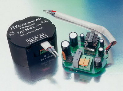
A SMPS viper12 a quality control sample for the use of integrated LED lighting can be used in different applications or .. have a nice design sizes quite small
DC output: 12 mA VDC/500
Efficiency: 75% typical
Input voltage: 90-264VAC 50-60 Hz
Dimensions: 57 x 49 x 32 mm
This network is designed for the assembly in sub-cleaning Junction boxes. With its output of 6 W (12 VDC/500 mA) can be almost any standard Power Supply through this discreetly in the wall installable version replaced. Whether as a power supply for surveillance cameras, wireless video transmission systems or small fan installation — the application are no limits.
VIPer12A SMPS Circuit

SMPS Controllers (Switch mode power suppl) IC 2, the circuit is quite clearly. The at the terminals supplied from KL 1 230 V AC is protected by the fuse, guided on the bridge rectifier. This makes the 230 VAC a DC voltage of about 320 V. This DC voltage is applied via the transformer TR 1 to the drain of the Switching regulator viper12a ICs. This IC contains all essential stages of a switching power supply. Then run the internal Oscillator which oscillates at 60 kHz. Also, the other internal stages active and the power MOSFET begins to switch. Limiting the drain Current is adjusted via an internal control circuit
Source: http://www.elv-downloads.de/service/manuals/SPS12UP/62121-SPS12UP.pdf 12V 500ma Switch Mode Power Supply Circuit VIPer12A alternative link:
Password: 320volt.com
Published: 2008/06/28 Tags: power electronic projects, smps circuits, smps projects, smps schematic
100W Hi Fi Mosfet Amplifier Circuit
Hello friends I made last year, I thought I’d start by modifying my work 2 +1. Modifying the power stage of the exchange, commissioned an active filter to be added and satellite signal input regulation of there work force with a solid start circuit located on the BDW transistors’ve done with 100w health circuitry to cancel and in lieu 100w a MOSFET operation will place. First, let’s take 100w circuit health