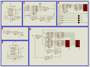
6 ‘s application circuits usually 74LS48 , 74LS192 , 74LS00 , 74LS175 , 74LS20 , 74LS02 TTL integrated and used in all the main logic integrated timing Lm555 same
1 and 5 Lm555 circuits are made with square wave oscillator circuit .
1 in the frequency of the circuit is greater than the frequency of the circuit 5 .
Phase 1 Phase 2 5.devr 6 oscillator circuit running circuit are providing
Phase 2 is used in D-type fli – flop integrated 74ls175 is endtegre . There are four units in flip-flops . D FF is a bit memory element . When the clock input to the output that transmits the information . Integrated and which is triggered on the rising edge of 74ls175 button when pressed about the clock output (Q ) is made low . Pressing any button on the doors of the clock signal circuit design is made to be cut .
Phase 3 of the information received 2 deactivate LEDs and 7-segment display is designed to be shown on . namely 2nd half as well which button pressed Phase 3 o the button corresponding LEDs on the burning 8to3 encoder IC ( 74ls148 ) come with 4 btlik information encoded after the NOT gate with terslenip 3to7 decoder IC ( 74ls48 ) and 3 -bit data code of soluble and in the display of a corresponding button number is seen .
By triggering the 5.devre received from 6.devr clockpals makes the process of counting 0-10 . 4 bits for this job up / down ( up / down) counter IC ( 74ls192 ) was used. Integrated ‘s up to each clock integrated in the applied input is counted up . and the door using two integrated circuits were asked to count to 10 .
U12 : B door integrated into the counting of the different outputs can be connected between 0-19 . integrate each 0-9 counts. Information received from the output with integrated decoder still 74ls48 7-segment display using the method demonstrated value is counted in the number .
2 to 4 and 6 of the circuit from any of circuits SINTAL designed to be activated when the buzzer . Hehang a button that when pressed or counter to count to 10 when the buzzer starts crowing .
This fact quiz complicated circuit is the same as used in the logic circuit .
of each competitor before you press the button if buttons are on the front which contestant lamp ( LED ) lights , buzzer, and the system locks itself by playing other boutiques makes passive ..
TTL Display Circuits


TTL integrated circuits with applications on the display proteus simulation files:
FILE DOWNLOAD LINK LIST (in TXT format): LINKS-13134.zip
Published: 2010/11/13 Tags: analog circuits projects
LED King Rider walking LEDs circuit 74LS163 74LS138
Also known as circuit king rider circuit. The signal applied to the circuit from the pulse generator with integrated 74ls163 74ls192 is triggered by controlling doors, and from there with the aid of information obtained by applying the LEDs 74ls138 right / left shift is provided.
0-16 inter-counting process that 74ls163 integrated Q3 output from the LOW signal and doors are controlled generator signals from the first 74ls192’n’s up input is applied to integrated upstream counted the 74ls138 integrated output of the LEDs on the right is shifted. 74ls163 When the count of nine Q3 output will be HIGH and doors 74ls192’n this time integrating the signal from the generator to the input of the implements and integrates down counting down. left shift of the LEDs is provided.
LED King Rider Circuit