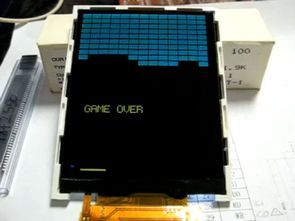
PIC24, PIC32 about not say anything, but generally TFT screen for the pic of the velocity of the poor is said to be already on the web the very avr, arm TFTs have applications in this sample pic programs of people who might come in handy software CCS C and prepared also the LCD driver file there (ssd1289.c)
PIC18F4680 TS8001 circuit test ;

SSD1289.c CCS C ;
/*
*************************************************************************************************
*     TFT LCD 262k Couleur , Controlleur Solomon system's SSD1289
*                              Tout droits réservé
* On va utiliser 65k couleur (16bits pour la rapidité)
* Nom fichier    : SSD1289.c
* Programmeur    : Muller F. , conversion en CCS C , ajout des fonctions graphiques.
*                              reprise et convertion de LCD_Init de Techtoys
* Note           : v1.0a
* Matériel       : PIC18F4680 , 32Mhz (Int_Osc 8Mhz , PLL X4)
* Date           : 15 Juin 2007
*************************************************************************************************
*                              DESCRIPTION
*
* Ce module est une interface pour l'ecran TFT 262k Couleur de 240 x 320 points
* Controllé par SSD1289
* L'ecran est alimenté en 3.3V, La LED d'eclairage de l'ecran consome 15mA
* La LED d'eclairage est alimenté par le CAT32 pour 15mA constant (FG020214_BO)
* <PS3:PS1:PS0> configuré en  <1:0:0> pour un bus de données de 8 bits en mode 8080
*
* Fonctions des broches du LCD sur la carte FG020214_BO (www.TechToys.com.hk)
* ---------   LCD              PIC -----------------
* pin 2      SHDN_BL  - Non utilisé ici, connecter à VCC avec une resistance de 100k
* pin 4       GND     - GND
* pin 6       VCC     - Alim 3.3V
* pin 10      WR      - RC0
* pin 12      RD      - RC1
* pin 14      CS      - RC2
* pin 16      CD      - RC6
* pin 18      RST     - Vers reset du CPU (MCLR du PIC)
* pin 20:34   D1:D8   - Port de données de l'ecran connecté à RD0:RD7
*
* Remarques : Les broches de nombre impair ne sont pas connectées en mode de données 8 bits
*
***********************************************************************************************
*/


/*
*************************************************************************************************
*                                 Definitions Locale
*************************************************************************************************
*/

typedef unsigned char       INT8U;
typedef unsigned int16      INT16U;

#include <FONT57.c>
#include <FONT812.c>
#include <image.c>

/*
*************************************************************************************************
*        Definition du Délais entre les pulses Haut et Bas sur les broche de l'écran
*        A 40Mhz 1 cycle = 100ns (10Mips) (Enlever les comments dans LCD_Cmd et LCD_Data
*        Inutile à 32Mhz et inférieur
*************************************************************************************************
*/

#define  att1           1

/*
*************************************************************************************************
*                                 Taille de l'ecran
*************************************************************************************************
*/
#define  GCLCDX         239
#define  GCLCDY         319
#define  X_START        0
#define  Y_START        0
#define  X_END          GCLCDX
#define  Y_END          GCLCDY

/*
*************************************************************************************************
*                                 Les Commandes du SSD1289
*************************************************************************************************
*/

// Utilisé dans init
#define OSC_START            0x00
#define DRIVER_OUT           0x01
#define LCD_DRIVE_AC         0x02
#define POWER_CONTROL1       0x03
#define POWER_CONTROL2       0x0C
#define POWER_CONTROL3       0x0D
#define POWER_CONTROL4       0x0E
#define POWER_CONTROL5       0x1E
#define DISPLAY_CONTROL      0x07
#define ENTRY_MODE           0x11
#define SLEEP_MODE           0x10
#define HORIZONTAL_RAM_START 0x44
#define VERTICAL_RAM_START   0x45
#define VERTICAL_RAM_END     0x46
#define RAM_WRITE            0x22
// Commandes complémentaires
#define LCD_X                0x4E
#define LCD_Y                0x4F


/*
***********************************************************************************************
* RGB en 16 bits, pour mode 65k couleurs
* [R4R3R2R1R0G5G4G3][G2G1G0B4B3B2B1B0]
***********************************************************************************************
*/
#define RGB16(r,g,b)   ((INT16U)r<<11)+(INT16U)g<<5)+(INT8U)b


/*
***********************************************************************************************
*                        Definition de quelques couleurs de base en 16 bits
***********************************************************************************************
*/

#define  NONE        0x0000      // Juste pour preciser qu'il n'y à pas de couleur

#define BLEU         0x001F
#define JAUNE        0xFFE0
#define ROUGE        0xF800
#define VERT         0x07E0
#define NOIR         0x0000
#define BLANC        0xFFFF
#define VERTCLAIR    0xEFE0
#define VERTFONCE    0XE0E0
#define ROUGEFONCE   0XF200
#define BLEUFONCE    0X000F
#define BLEUCLAIR    0X07FF
#define ORANGE       0XF8E0
#define MAUVE        0XF81F

/*
***********************************************************************************************
*                        Definition des broches , CCS C
*                        Materiel : PIC18F4680
***********************************************************************************************
*/
#define  glcd_wr             PIN_C0
#define  glcd_rd             PIN_C1
#define  glcd_cs             PIN_C2
#define  glcd_cd             PIN_C6
// LCD Data port D1:D8 --> PIC Port D0:D7


/*
***********************************************************************************************
*                              Constantes Globale
***********************************************************************************************
*/

#define YES                1
#define NO                 0
#define HIGH               1
#define LOW                0

/*
***********************************************************************************************
*                           Definition des fonctions
***********************************************************************************************
*/

void LCD_Init(void);
void LCD_CLS(INT16U couleur);
void LCD_Cmd(INT8U cmd);
void LCD_Data(INT8U dat);
void LCD_Fillscreen(INT8U x1, INT16U y1, INT8U x2, INT16U y2,INT16U couleur);
void LCD_Pixel(INT8U x , INT16U y , INT16U couleur);
void LCD_Ligne(INT8U x1 , INT16U y1 ,INT8U x2 , INT16U y2 , INT16U couleur);
void LCD_Rect(INT8U x1, INT16U y1, INT8U x2, INT16U y2, int1 plein, INT16U couleur);
void LCD_Cercle(INT8U x, INT16U y, INT16U rayon, int1 plein, INT16U couleur);
void LCD_Text57(INT8U x, INT16U y, char* textptr, char Taille, INT16U couleur, INT16U couleur_arriere);


/*
*************************************************************************************************
*                                     DISPLAY INITIALIZATION
*
* Description : This function initializes the LCD module
* Arguments   : none
*
* Returns     : none
* Note        : This function should be called once before any of the other functions
*************************************************************************************************
*/
void LCD_Init(void)
{

   // Set the cmd port
   Set_Tris_C(0x00);   // Port_C all outputs
   // Set the data port
   Set_Tris_D(0x00);   // Port_D all outputs
   // Set all bit from Port C and D to 0
   Output_C(0x00);
   Output_D(0x00);

   // Start screen initialisation

   LCD_Cmd(OSC_START);          //Start Oscillation
   LCD_Data(0x00);
   LCD_Data(0x01);

   LCD_Cmd(DRIVER_OUT);         //Driver Output Control
   LCD_Data(0x23);
   LCD_Data(0x3F);

   LCD_Cmd(LCD_DRIVE_AC);       //LCD Drive AC Control
   LCD_Data(0x06);
   LCD_Data(0x00);

   LCD_Cmd(POWER_CONTROL1);     //Power Control (1)
   LCD_Data(0xA8);
   LCD_Data(0xA6);

   LCD_Cmd(DISPLAY_CONTROL);    //Display Control
   LCD_Data(0x00);
   LCD_Data(0x33);

   LCD_Cmd(ENTRY_MODE);         //Set Display color mode for 65k color
   LCD_Data(0x68);
   LCD_Data(0x30);

   LCD_Cmd(POWER_CONTROL2);     //Power Control (2)
   LCD_Data(0x00);
   LCD_Data(0x05);

   LCD_Cmd(POWER_CONTROL3);     //Power Control (3)
   LCD_Data(0x30);
   LCD_Data(0x0B);

   LCD_Cmd(POWER_CONTROL4);     //Power Control (4)
   LCD_Data(0x20);
   LCD_Data(0x00);

   LCD_Cmd(SLEEP_MODE);         //Exit Sleep Mode
   LCD_Data(0x00);
   LCD_Data(0x00);
   Delay_Ms(30);                //delay 30ms

   LCD_Cmd(POWER_CONTROL5);     //Power Control (5)
   LCD_Data(0x00);
   LCD_Data(0xA8);

   LCD_Cmd(HORIZONTAL_RAM_START);   //Horizontal RAM address position start/end setup
   LCD_Data(0xEF);                  //decimal 239
   LCD_Data(0x00);                  //decimal 0, i.e. horizontal ranges from 0 -> 239
                                    //POR value is 0xEF00 anyway. This address must be set before RAM write

   LCD_Cmd(VERTICAL_RAM_START);     //Vertical RAM address start position setting
   LCD_Data(0x00);                  //0x0000 = decimal 0
   LCD_Data(0x00);

   LCD_Cmd(VERTICAL_RAM_END);       //Vertical RAM address end position setting
   LCD_Data(0x01);                  //0x013F = decimal 319
   LCD_Data(0x3F);

   LCD_Cmd(RAM_WRITE);              //Commande d'ecriture dans la Memoire ecran

   LCD_CLS(BLANC);                  //initialize le LCD en couleur Blanche (mode 16 Bits)
}

/*
*************************************************************************************************
*                            Effacer tout l'ecran en mettant tout les pixels
*                             à la couleur passé en argument (mode 16Bits)
*
* Arguments   : 'couleur' format 16 bits RGB16(r,g,b)(mode 565)
*                                    [R4R3R2R1R0G5G4G3][G2G1G0B4B3B2B1B0]
*            Pour (r,g,b) de (0,0,0) à (31,63,31)
*************************************************************************************************
*/
void LCD_CLS(INT16U couleur)
{
   INT8U i,hiByte,lowByte;
   INT16U j;

   hiByte  = couleur>>8;
   lowByte = (INT8U)couleur;

   for(j=0;j<320;j++)
   {
      for(i=0;i<240;i++)
      {
         LCD_Data(hiByte);LCD_Data(lowByte);
      }
   }
}

/*
*************************************************************************************************
*                                     Envoyer une commande à l'écran
*************************************************************************************************
*/
void LCD_Cmd(INT8U cmd)
{
   Output_D(cmd);
   //delay_cycles(att1);
   output_bit(glcd_cd,LOW);       //CD LOW pour commande
   //delay_cycles(att1);
   output_bit(glcd_wr,LOW);
   //delay_cycles(att1);
   output_bit(glcd_rd,HIGH);
   //delay_cycles(att1);
   output_bit(glcd_cs,LOW);
   //delay_cycles(att1);
   output_bit(glcd_cs,HIGH);
   //delay_cycles(att1);
}
/*
*************************************************************************************************
*                                     Envoyer une donnée 8 bits à l'écran
*************************************************************************************************
*/
void LCD_Data(INT8U dat)
{
   Output_D(dat);
   //delay_cycles(att1);
   output_bit(glcd_cd,HIGH);      //CD HIGH pour display data
   //delay_cycles(att1);
   output_bit(glcd_wr,LOW);
   //delay_cycles(att1);
   output_bit(glcd_rd,HIGH);
   //delay_cycles(att1);
   output_bit(glcd_cs,LOW);
   //delay_cycles(att1);
   output_bit(glcd_cs,HIGH);
   //delay_cycles(att1);
}

/*
*************************************************************************************************
*                                     Afficher un point dans l'écran
*   x       : 0 à 239
*   y       : 0 à 319
*   couleur : format 16 bits RGB16(r,g,b)
*************************************************************************************************
*/

void LCD_Pixel(INT8U x , INT16U y , INT16U couleur)
{
   INT8U hiByte, lowByte;

   hiByte  = y>>8;
   lowByte = (INT8U)y;

   LCD_Cmd(LCD_X);                                 // coordonnée X
   LCD_Data(0x00);                                 // Coordonnée toujours en 16bits (bit de poid
                                                   // fort en 1er (0x00 pour 'x' qui est en 8 bits
   LCD_Data(x);
   LCD_Cmd(LCD_Y);                                 // coordonnée Y
   LCD_Data(hiByte);
   LCD_Data(lowByte);
   hiByte  = couleur>>8;
   lowByte = (INT8U)couleur;
   LCD_Cmd(RAM_WRITE);
   LCD_Data(hiByte);LCD_Data(lowByte);
}


/*
*************************************************************************************************
*                                     Tracer une ligne dans l'écran
*   x1      : 0 à 239   : debut x
*   y1      : 0 à 319   : debut y
*   x2      : 0 à 239   : fin x
*   y2      : 0 à 319   : fin y
*   couleur : format 16 bits RGB16(r,g,b)
*************************************************************************************************
*/
void LCD_Ligne(INT8U x1 , INT16U y1 ,INT8U x2 , INT16U y2 , INT16U couleur)
{
   int16        dy, dx;
   signed int8  addx=1, addy=1;
   signed int16 P, diff;

   int16 i=0;
   dx = abs((signed int8)(x2 - x1));
   dy = abs((signed int16)(y2 - y1));

   if(x1 > x2)
      addx = -1;
   if(y1 > y2)
      addy = -1;

   if(dx >= dy)
   {
      dy *= 2;
      P = dy - dx;
      diff = P - dx;

      for(; i<=dx; ++i)
      {
         LCD_Pixel(x1, y1, couleur);

         if(P < 0)
         {
            P  += dy;
            x1 += addx;
         }
         else
         {
            P  += diff;
            x1 += addx;
            y1 += addy;
         }
      }
   }
   else
   {
      dx *= 2;
      P = dx - dy;
      diff = P - dy;

      for(; i<=dy; ++i)
      {
         LCD_Pixel(x1, y1, couleur);

         if(P < 0)
         {
            P  += dx;
            y1 += addy;
         }
         else
         {
            P  += diff;
            x1 += addx;
            y1 += addy;
         }
      }
   }
}

/*
*************************************************************************************************
*                                     Rempli une partie de l'écran
*   x1      : 0 à 239   : debut x
*   y1      : 0 à 319   : debut y
*   x2      : 0 à 239   : fin x
*   y2      : 0 à 319   : fin y
*   couleur : format 16 bits RGB16(r,g,b)
*************************************************************************************************
*/
void LCD_Fillscreen(INT8U x1, INT16U y1, INT8U x2, INT16U y2,INT16U couleur)
{
   int16 i;

   for(i=y1; i<y2; i++)
   {
      LCD_Ligne(x1 , i , x2 , i , couleur);
   }
}


/*
*************************************************************************************************
*                                     Tracer un Rectangle dans l'écran
*   x1      : 0 à 239   : debut x
*   y1      : 0 à 319   : debut y
*   x2      : 0 à 239   : fin x
*   y2      : 0 à 319   : fin y
*   plein   : YES ou NO (rectangle plein ou vide)
*   couleur : format 16 bits RGB16(r,g,b)
*************************************************************************************************
*/
void LCD_Rect(INT8U x1, INT16U y1, INT8U x2, INT16U y2, int1 plein, INT16U couleur)
{
   if(plein)
   {
      int16 y, ymax;                          // Trouver  y min et max
      if(y1 < y2)
      {
         y = y1;
         ymax = y2;
      }
      else
      {
         y = y2;
         ymax = y1;
      }

      LCD_Fillscreen(x1,y,x2,ymax,couleur);  // Trace un rectangle plein
   }
   else
   {
         LCD_Ligne(x1, y1, x2, y1, couleur);
         LCD_Ligne(x1, y2, x2, y2, couleur);
         LCD_Ligne(x1, y1, x1, y2, couleur);
         LCD_Ligne(x2, y1, x2, y2, couleur);
   }
}

/*
*************************************************************************************************
*                                     Tracer un Cercle dans l'écran
*   x1      : 0 à 239   : debut x
*   y1      : 0 à 319   : debut y
*   rayon   :Rayon du cercle
*   plein   : YES ou NO (cercle plein ou vide)
*   couleur : format 16 bits RGB16(r,g,b)
*************************************************************************************************
*/
void LCD_Cercle(INT8U x, INT16U y, INT16U rayon, int1 plein, INT16U couleur)
{
   signed int16 a, b, P;
   a = 0;
   b = rayon;
   P = 1 - rayon;

   do
   {
      if(plein)
      {
         LCD_Ligne(x-a, y+b, x+a, y+b, couleur);
         LCD_Ligne(x-a, y-b, x+a, y-b, couleur);
         LCD_Ligne(x-b, y+a, x+b, y+a, couleur);
         LCD_Ligne(x-b, y-a, x+b, y-a, couleur);
      }
      else
      {
         LCD_Pixel(a+x, b+y, couleur);
         LCD_Pixel(b+x, a+y, couleur);
         LCD_Pixel(x-a, b+y, couleur);
         LCD_Pixel(x-b, a+y, couleur);
         LCD_Pixel(b+x, y-a, couleur);
         LCD_Pixel(a+x, y-b, couleur);
         LCD_Pixel(x-a, y-b, couleur);
         LCD_Pixel(x-b, y-a, couleur);
      }

      if(P < 0)
         P+= 3 + 2*a++;
      else
         P+= 5 + 2*(a++ - b--);
    } while(a <= b);
}

/*
*************************************************************************************************
*                                     Tracer un texte avec la Fonte 5 x 7 points
*   x1      : 0 à 239
*   y1      : 0 à 319
*   Taille  : Utiliser 1 pour la taille normale , ou >1 pour agrandir les caracteres
*   couleur         : format 16 bits RGB16(r,g,b)    ** Couleur des caractere
*   couleur_arriere : format 16 bits RGB16(r,g,b)    ** Couleur d'arriere plan des caracteres
*************************************************************************************************
*/
void LCD_Text57(INT8U x, INT16U y, char* textptr, char Taille, INT16U couleur, INT16U couleur_arriere)
{
   int8 j, k, l, m;                                        // Compteurs
   int8 pixelData[5];                                      // enregistre les données du caractere

   for(; *textptr != '\0'; ++textptr, ++x)                 // Compter jusqu'a la fin du texte
   {
      if(*textptr < 'S') // Regarde si le caractere est stocké dans le 1er tableau de chaine
         memcpy(pixelData, FONT[*textptr - ' '], 5);
      else if(*textptr <= '~') // Regarde si le caractere est stocké dans le 2eme tableau de chaine
         memcpy(pixelData, FONT2[*textptr - 'S'], 5);
      else
         memcpy(pixelData, FONT[0], 5);   // Si caractere non trouvé alors considerer comme espace

       // Retour a la ligne et nouvelle ligne
      switch(*textptr)
      {
         case '\n':
            y += 7*Taille + 1;
            continue;
         case '\r':
            x = 0;
            continue;
      }

      if(x+5*Taille > X_END)                                        // Performs character wrapping
      {
         x = 0;                                                     // Set x at far left position
         y += 7*Taille + 1;                                         // Set y at next position down
      }
      for(j=0; j<5; ++j, x+=Taille)                                 // Loop through character byte data
      {
         for(k=0; k < 7; ++k)                                       // Loop through the vertical pixels
         {
            if(bit_test(pixelData[j], k))                           // Check if the pixel should be set
            {
               for(l=0; l < Taille; ++l)                            // These two loops change the
               {
                  for(m=0; m < Taille; ++m)
                  {
                     LCD_Pixel(x+m, y+k*Taille+l, couleur);         // Draws the pixel
                  }
               }
            }
            else if (couleur_arriere != NONE)
            {
               for(l=0; l < Taille; ++l)                            // These two loops change the
               {                                                    // Pixel back color
                  for(m=0; m < Taille; ++m)
                  {
                     LCD_Pixel(x+m, y+k*Taille+l, couleur_arriere); // Draws the pixel
                  }
               }
            }
         }
      }
   }
}
Source: cvtelectronics.com Alternative link:
FILE DOWNLOAD LINK LIST (in TXT format): LINKS-13901.zip
Published: 2011/01/30 Tags: microchip projects, microcontroller projects
AVR ISP USB Programmer Circuit ATmega8
Previously shared AVR set of experiments found in the AVR ISP programmer carried out separately version of all materials the same printed circuit board size is small circuit for the USB connection FT232RL used programmer ATMEGA8 based on avrprog AVR Studio, Bascom AVR programs can work with. ATmega8 USB Programmer
ATMega8 first integrated circuit to the programmer to main hex file needed to install