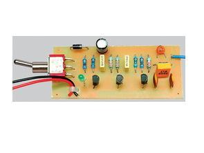
3 transistors are used (bc548) supply voltage is 9 volts 455kHz RF signal is produced with ceramic crystal.
Description of the circuit
The 455kHz Modulated Oscillator generates an amplitude modulated 455kHz carrier waveform with a 500Hz tone. You can use it to align the intermediate frequency (IF) stages of any AM broadcast or shortwave radio.
This project generates amplitude modulated 455kHz RF signal. It can be used to accurately align the intermediate frequency stages of heterodyne AM receivers.

If you are going to build the Aussie 3-Valve Radio described in this issue or are involved in restoring old radios, you will want to correctly align the IF stages of this Minispot 455kHz modulated oscillator. For readers with long memories, it looks a lot like the Minispot circuit published in the February 1981 issue of “Electronics Australia” magazine.
The goals of IF alignment are to ensure that all tuned circuits in the IF stages are tuned to the same frequency and that this frequency is the correct frequency, usually 455 kHz.
If the various parts of the IF stages are tuned to different frequencies, the sensitivity of the receiver is poor. It may also encounter unwanted loud whistles at the sound output. Therefore, correct IF compatibility is essential for good performance.
Oscillator Circuit

Source: http://www.siliconchip.com.au/cms/A_109838/article.html
455kHz Oscillator Circuit pcb schematic alternative link:
Password: 320volt.com
Published: 2008/09/03 Tags: analog circuits projects
Alcoholmeter Circuit with MG3 Sensor LM3914 LED Display Indicator
MG3, LM3914 example with a different voltage level than the volume of water level can be used in many applications Usage Sensor for measuring alcohol levels MG-3 LEDs, the LM3914 output level is observed in the 10 to 12 volts dc supply voltage
MG3 Alcoholmeter Circuit