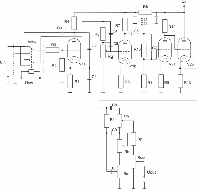
The involvement of the preamplifier This is a long-established involvement with tubes type ecc83. This involvement is used by legendary guitar amps Marshall JCM 800
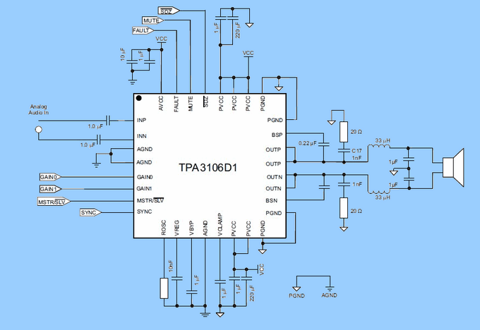
After studying the issue, I decided for the implementation of digital audio amplifier using the circuit TPA3106 D1 of the firm Texas Instruments. The picture sleeve is located on the fig. 7, In came into consideration also the circuits of the company Maxim, however, the parameters of the circuits they were not so interesting. In the selection I was making this decision according to several aspects, and according to the the size and type of housing, so this housing in order to later implement on the board pcb, output performance, which has a sufficient safety margin in low-distortion signal, the opportunity to work in 4 ! i 8 ! burden, the signal to noise ratio, and many others. An important the argument also was that the manufacturer provides test samples for free.
Class-D Power Amplifier TPA3106D1 Circuit

The selected digital class d audio amplifier TPA3106 D1 is monophonic with a maximum an output power of 40 Watts. This integrated circuit also includes protection against overheating and short circuit protection of the output circuit. After short-circuiting the output of the amplifier is the output of the amplifier automatically disconnected, and this state is indicated by the TTL logic signals to the other circuits. The circuit can also work with other audio amplifiers of the same class. Amplifier it can therefore operate in two modes, Master or Slave. In Master mode, this amplifier the managing member and generates a basic control signal (clock signal) for the other audio the amplifiers, which are in Slave mode. This way you can design a multi-channel amplifier composed of multiple circuits. The amplifier operates with a supply voltage in the range of from 10 to 26 In and is possible to use even in automotive technology.


The frequency of the pulse code modulation is adjustable in the range from 200 kHz to 300 kHz. Pulse code modulation. The duty cycle of the output pulses varies depending on the frequency of the input analog signal. After filtration of the high-frequency components by a filter type low-pass filter we get on the output of the amplifier, again an analog signal. Circuit TPA3106 D1 is the manufacturer comes in housing HLQFP, which has 32pinové arrangement of inputs and outputs. In the implementation itself the circuit I came out of the engagement, which the manufacturer recommends in the datasheet of the integrated circuit.
![]() TPA3106 D1 class d amp pcb schematic all files alternative links:
TPA3106 D1 class d amp pcb schematic all files alternative links:
FILE DOWNLOAD LINK LIST (in TXT format): LINKS-25491.zip
Published: 2016/06/05 Tags: audio amplifier circuits, class d amplifier circuit, ic amplifier
Simple soft start Circuit 220V
Especially high value capacitors used for power supply, soft start circuit in SMPS circuits 220v line that is used in this circuit one 220V, we also like a lot of trafos is designed to operate directly having a simple structure by regulating.
smps high power SMPS PCB design printed circuit board was kept as small as possible or different or may be helpful in your projects.
TPA3106D1 Class-D-Verstärker Projekte Ecc83 JCM800 Vorverstärker
Die Einbeziehung des Vorverstärkers Dies ist eine seit langem etablierte Beteiligung mit Röhren Typ ecc83. Diese Beteiligung wird von der legendären Gitarren-Verstärker Marshall JCM 800
Nach dem Studium das Problem, entschloss ich mich für die Umsetzung von digitalen audio-Verstärker verwenden der Schaltung TPA3106 D1 von der Firma Texas Instruments. Das Bild Hülse befindet sich auf der Abb. 7, In der in Frage kam auch die schaltungen von der Firma Maxim, die Parameter der schaltungen waren Sie nicht so interessant. Bei der Auswahl war ich diese Entscheidung nach mehreren Aspekte, und nach der Größe und Art der Unterbringung, also das Gehäuse, um später die Umsetzung des board-pcb, output-Leistung, die eine ausreichende Sicherheitsmarge in der low-distortion-signal, Gelegenheit zur Arbeit in 4 ! ich 8 ! Last -, signal-zu-Rausch-Verhältnis, und viele andere.