Class D Amplifier TDA8927J This integrated circuit includes a terminal switching transistors type DMOS (Double-Diffused MOS), circuits for controlling the transistors and circuits for communication with the control circuit. It is also equipped with a control circuit for detecting the maximum output current and temperature sensor. Further, this circuit is characterized by high efficiency, a relatively large supply voltage range, a small stalled shock and as already mentioned, it also includes thermal protection and protection against short circuit of output terminals.
TDA8929T This integrated circuit contains (for two audio channels) two pulse width modulators (PWM), two analog feedback loops and two input differential amplifiers. Furthermore it contains circuits common to both channels such as the oscillator, all reference sources and control circuits.
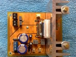
Class D Amplifier TDA8927J TDA8929T Circuit

The analog signal is applied to the inputs of differential amplifiers, which signal amplifies with a fixed gain of 30dB. Thus amplified signals are further brought to the non-inverting inputs of comparators and compared with the triangle signal from the internal oscillator. At the output of the comparator creates the PWM signal, which is connected to the output pins SW1 and SW2. The oscillator frequency is set by resistor ROSC connected between pin OSC and a negative power supply voltage VSS This frequency can be calculated according to the relation.

Pin MODE allows you to switch the system between different modes of operation (STAND by, MUTE and OPERATING). The settings of the individual modes is indicated in figure 3.3. In the mode of OPERATING is right the switch is closed and the pin MODE is applied the voltage of +5V. For mode STAND by must be both switches rozepnuty. Pin MODE is thus connected to ground (GND). For the mode MUTE is switched the left switch. In this mode, will only occur to inhibit the output audio signal.


![]() class d amp project pcb schematic all files alternative links:
class d amp project pcb schematic all files alternative links:
FILE DOWNLOAD LINK LIST (in TXT format): LINKS-25577.zip
Published: 2016/06/07 Tags: audio amplifier circuits, class d amplifier circuit, ic amplifier
12V 40A Switch Mode Power Supply LLC Resonant Converter
NCP5106A NCP1396A Detailed study the principles of operation of the serial, parallel and serial-parallel resonant LLC Converter. Think about the possible organization of multiphase serial-parallel Converter LLC SMPS . WITH using math and simulation tools compare the current design of the individual Power devices, single-phase and multiphase versions of the inverter. Carry out a theoretical proposition two-stage serial-parallel LLC converters with output parameters 12 V / 40 A and include a comparison with its monophasic variant. Based on the theoretical design build functional sample the frequency and will compare its parameters with the theoretical suggestions.
TDA8929T TDA8927J Klasse-D Verstärker Schaltung Projekt
Klasse-D-Verstärker TDA8927J Diese integrierte Schaltung enthält einen terminal-switching-transistoren type DMOS (Double-Diffused MOS), schaltungen für die Ansteuerung der transistoren und schaltkreise für die Kommunikation mit dem control-Schaltung. Es ist auch ausgestattet mit einem Kontroll-Schaltung für die Erkennung der maximale Ausgangsstrom und Temperatur-sensor. Weitere, diese Schaltung zeichnet sich durch hohe Effizienz, einen relativ großen Bereich der Versorgungsspannung, ein kleines stocken Schock und wie bereits erwähnt, es enthält auch Thermoschutz und Schutz gegen Kurzschluss der Ausgangsklemmen.
TDA8929T Diese integrierte Schaltung enthält (für zwei audio-Kanäle), zwei pulse-width-Modulatoren (PWM), zwei analoge feedback-Schleifen und zwei Eingangs-differenzverstärker. Des weiteren enthält schaltungen gemeinsam für beide Kanäle, wie den Oszillator, alle Bezugsquellen und Regelkreise.