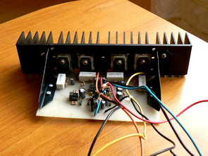
TDA7250 power output stage The main element of the offered power stage is a custom TDA7250 integrated circuit from SGS Thomson. It is a complete two-channel power transistor driver that enables the creation of a stereo power amplifier. Using the manufacturer’s catalog data, two pairs of complementary TIP142, TIP147 transistors were selected to work with it. With a supply voltage of +/-35V, they provide 70W per channel for an 8 Ohm load.
The presented device works with a voltage of +/- 37V, which allows you to reach 110W with a load of 4 Ohms. The controller system is equipped with circuits for short-circuit protection, PLAY, STANDBY and MUTE functions as well as automatic regulation of the quiescent current of the transistors. The absence of built-in thermal protection necessitated the installation of such a system, which is presented and described later in this description.


The outputs of the first channel are OUT+CH1 and OUT-CH1 which control the complementary stage consisting of Darlighton transistors Q1, Q2. Resistors R16, R6, connected to these transistors provide the TDA7250 system with monitoring inputs 17, 4, which contain information about the instantaneous value of the current flowing in the collectors of the transistors. The system uses this information to automatically set the quiescent current and short circuit protection of the last stage. If the voltage drop across resistors R16, R6 exceeds 1V, the system detects this as a short circuit and cuts off the transistor control signal via the internal flip-flops.
The signal from the amplifier output via R11 and C9 goes to the inverter input of the U1 system (pin, 20), which closes the feedback loop. The feedback signal is fed to the non-inverting input of the input amplifier through capacitor C28 and the input signal through capacitor C26. Capacitor C26 blocks the flow of the DC component in the input circuit and resistor R19 polarizes the input stage and together with C27 suppresses the input excess acoustic components. The components connected to inputs 3 and 8 form integrated circuits that protect against rapid changes in static current. If the voltage at input 8 drops below 250mV, the TDA7250 will reset.
During cut-off, for example, when drawing too much current, the control outputs go into a high-impedance state. For the system to return to working condition, the voltage at input 8 must drop below 250mV; this is achieved by discharging capacitor C23 through resistor R22. The operation of the second channel is the same, therefore its description has been omitted. The U1 system is equipped with STAND-BY, MUTE, PLAY functions, these are controlled by applying the appropriate voltage level to the control foot (pin 5).
The voltage supplied to the 5th leg of the U1 (TDA7250) system through the voltage divider R28, R36 causes this system to perform the PLAY function. When the microprocessor control signal is applied to the OP1A optocoupler, the system enters the STANDBY state. This causes the resistor R27 to be connected in parallel to R36 through the internal transistor of the OP1A system, as well as a change in voltage supplied to the control input of the TDA7250 system. Elements R35 and OP1B are responsible for the transition of the system to the MUTE state and R32.
and R33 limits the currents flowing through the emitting diodes of the optocouplers. The regulation of the functions of the U1 system is done by changing the voltage with respect to -Vs, so optoisolation must be used to separate the mass of the control system (microprocessor) from the voltage -Vs. Note that the values of the control voltages may differ slightly, so sometimes it is necessary to change the values of the divider elements.

Thermal protection
The TDA7250 driver used does not have a thermal protection system for the power transistors, a system had to be made to perform this function.
As the temperature sensor, an RT1 thermistor mounted on a heatsink was used next to the power transistors. If the voltage at input 2 of the U4A system drops below the threshold set by P1 under the influence of temperature, a high state will appear at the output of U1A (voltage close to the power supply). This will cause relay PK1 to trip via T1 and disconnect the last stage power supply.
If the temperature returns to normal, a voltage close to ground will appear at the U1A output. Therefore, to completely block T1, the voltage across the divider R5, R6 is reduced. The positive feedback provided by the resistor R4 creates a small hysteresis, preventing the relay from tripping with a small change in temperature. Diode D1 protects the transistor against overvoltages that occur when relay PK1 is switched. The protection will be activated after the radiator exceeds the set temperature of approximately 80oC. The thermal protection activation is signaled by the optocoupler, which outputs a signal to the Inf output, this output must be connected to the control microcontroller or use an LED diode as the Optocoupler, which indicates that the protection is activated.
Hi-Fi Power Amplifier 100W with Driver TDA7250 Schematic PCB
Password: 320volt.com
Published: 2008/09/23 Tags: audio amplifier circuits, transistor amplifier
Microcontroller Controlled Metal Detector Projects
Result of displays in the form of two scales, which are estimated to judge the material goal.In addition, the screen is small scale level of response and the current supply voltage. PIC18F252 The program is intended for controller PIC18F252.The controller PIC16F873 (A) to this version can not be used. This is more demanding to resources controller. 252nd compatible controller on “pins” with 873 – m and can be programmed by the same programmer. The program workable only with korzinochnymi reels! R21 For this firmware needed zakorotit resistor R21 (in the old version of the scheme). In this version the appointment of buttons changed to read
PIC16F873A Metal Detector Clone PI