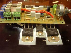
I think there is no one who knows the 200w amplifier circuit, whose power is increased by connecting 2 TDA2030 power transistors to its outputs. I first saw this circuit in the elektor in the 2000s. There was a thin and long PCB printed circuit drawing. It worked very well. Actually, my purpose in making the circuit was to evaluate the transformer I had. Since the circuit worked from a single source, it worked for me. I used the 12v circuit… You can operate it with a supply between .36v.

However, its efficiency is not good with 12v, the best work is between 24v….36v, my suggestion is to use at least 20v supply. Anyway, let’s come to the new printed circuit, I decided to re-do this circuit, but the first PCB I made did not look nice at all anymore 🙂
I did some research on the internet and found a much more organized drawing, but the leg connections of the transistors used in this drawing are non-standard (BD508, BD705), the bases and emitters are in the opposite direction, and I did not like some parts of the drawing, so I drew the printed circuit again, it was more organized in the new drawing, in addition, the inputs and outputs. I made it through terminal blocks and added fuses to the supply and speaker output line, and the size was smaller.


As I said, I did not get 12v to 24v with a yield tests worked fine for power transistors TIP35C, I used tip36c bd249 bd250 used instead.

PCB (tda2030-yeni-pcb.LAY) “Sprint-Layout-Viewer” http://www.abacom-online.de/uk/html/dateien/demos/viewlayout50.exe
Password: 320volt.com
Published: 2011/11/20 Tags: audio amplifier circuits, ic amplifier
Digital Analog Graphic LCD Clock Circuit MCB1700 LPC1768
LPC1768 RTC is related applications and graphic LCD with analog clock circuit application remain in me because I made such an application. I use armor kits Keil MCB 1700 dir.saat tuning kit for use on the joystick section, I `key1 to move to adjust the hold down for approximately 2 seconds to exit the adjustment portion is enough to press the button whilst INT0. I’ve helped friends interested in these issues.
Impressive. Does it require a cooler fan?
Can I use two c5200 and two A1943 transistors using the output of ordinary TDA2030 circuit as their input? I suggest you get someone good in English to edit your work. Otherwise great content.
When I give the circuit 18 volts the power transistors get really hot . Is it normal? Any idea What did i fucked up ?
Hello, not normal. Operating voltage between 12V-DC …… 36V-DC. check your circuit there may be a short circuit or faulty material
what the Passworld sir?
Hi, pass.: 320volt.com