I tested a working amplifier circuit TDA1562Q made with two pieces of the price a little expensive, but the performance is pretty good, stereo want to use
Car Amplifier circuit wiring diagram TDA1562Q

Note: For the sake of clarity of the drawing next to the socket erased some elements of this transaction was done just to make it look neat circuit wiring diagram is as in the original file
With very few passive components can make a quality car amp tda1562q
2x70W car amplifier with TDA1562Q
It is a class H stereo power amplifier with two philips TDA1562Q integrated circuits. Supply voltage is 8-18V, output power 55W continuous, 70W peak, peak consumption 6A, load impedance 4 ohms. Unlike some final products, the amplifier delivers a fair output of at least 55 W. Many amplifiers have declared outputs of the order of hundreds of watts, but the real output is usually less than 20 W.
Up to a power of 18 W, the final stage works as a standard bridge amplifier in class B. When the power is increased above 18 W, the voltage from the auxiliary capacitors C2 (C22) and C3 (C33) is connected, which are connected to two internal converters, and the amplifier works in class H .One inverter adds +12 V to the positive supply terminal and the other inverter capacitor connects to the negative supply terminal.
Theoretically, the amplifier is powered by a voltage of 36 V, i.e. ±18 V – of course, the saturation voltage on the converter’s transistors still needs to be subtracted. At this power supply, the standard output is 55 W, with very little distortion of 0.5%. Peak power reaches up to 70 W at up to 10% distortion. When the case temperature exceeds 120 °C, the internal inverters are disconnected and the amplifier goes into standard class B operation with a maximum power of up to 18 W. If the case temperature exceeds 145 °C, then the amplifier is completely disconnected. Due to switching operation, the amplifier can use a smaller heatsink than a classic amplifier of the same power. The amplifier also has very effective protection against short-circuiting of the output to ground and against the positive power supply, and of course also against short-circuiting of the outputs to each other. After removing the short circuit, the amplifier will restart in 20 ms.
SL1 serves to connect a stereo signal, if you do not use a preamplifier, connect to SL2 and SL3 a 100Kohm tandem linear potentiometer for volume control, resistors R2 (R22) ensure the logarithmic progression of the potentiometer. If you use a preamplifier (for example, TDA1524 ), connect the output from the preamplifier to SL1 and connect terminals SL2-3,2 and SL3-3,2 with wire jumpers, resistor R2 (R22) must not be connected!
The M-SEL input is used to turn off the amplifier, for easier control of the amplifier without the need to use a power switch, and the problem is solved by the amplifier still being powered and only switching on to Stand By mode. Applying a positive level to the M-SEL input makes the amplifier active. At zero voltage at this input, the amplifier switches to Stand by mode, when it consumes a maximum of 50 µA. The transition time between the two states is about 50 ms. However, components R4 and C8 increase this time.
The entire amplifier is powered from a car battery or alternator with a voltage range of 12 – 14.4V. The advantage of this power supply is that both voltage sources are very hard sources and supply a constant voltage while drawing a current of up to 6A, which the amplifier needs at full excitation.
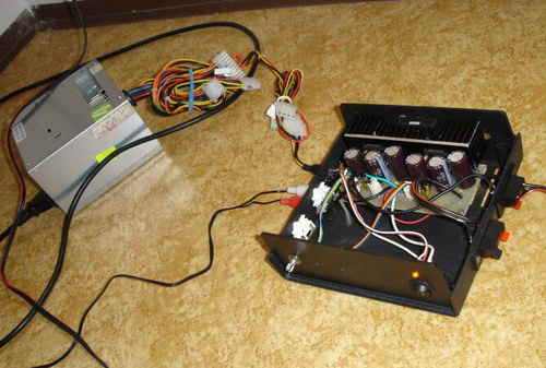
When using an amplifier outside the car, it is necessary to ensure a good source, especially a constant voltage of at least 12V and the possibility of drawing a current of up to 6A. It is best to use a car battery, but this solution is not ideal for continuous operation, for example somewhere in the home, because the car battery needs to be recharged. Another solution is the use of a transformer, which must deliver a large current. Winding the transformer will cost more money, but it is the most ideal for home use. Another option is to connect the amplifier to a source from the computer, which supplies up to 10A. It is the cheapest variant of the source, which amply suffices the amplifier.
The amplifier has a simple shutdown system. Components R4 and C8 ensure silent connection. Applying a positive voltage to the ST-BY input activates the amplifier. This voltage can be connected with an external switch or the ST-BY input is connected to the external control output of the car radio for switching on the amplifier. A small popping sound is heard in the speaker when the amplifier is turned off.
TDA1562Q Mono Amplifier Op Amp Preamp

source : chrudim2000.cz
All tda1562q circuits alternative link (mono-stereo)
Password: 320volt.com
Published: 2008/02/24 Tags: audio amplifier circuits, ic amplifier
Gradual Subwoofer Bass Filter Circuit
Circuit MC33074 (Operational Amplifiers) and PT2351 (Subwoofer Crossover Low Pass Filter) based on 55Hz and 65Hz 75Hz 85Hz 95hz 6 Step Switchgear 105Hz stage material can be selected by changing the values you can use different frequency
TDA1562Q Auto-Verstärkerschaltung
Ich habe eine funktionierende Verstärkerschaltung TDA1562Q getestet, die mit zwei Teilen des Preises ein wenig teuer ist (8,10 YTL Nähe), aber die Leistung ist ziemlich gut, Stereo verwenden wollen
Schaltplan der Auto-Verstärkerschaltung TDA1562Q
Hinweis: Aus Gründen der Übersichtlichkeit der Zeichnung neben dem gelöschten Sockel wurden einige Elemente dieser Transaktion ausgeführt, um das Erscheinungsbild des Schaltplans wie in der Originaldatei zu verbessern
Mit sehr wenigen passiven Bauteilen lässt sich ein hochwertiger Auto-Verstärker tda1562q herstellen