TDA1558Q 4×11 watt amplifier circuit can be installed with very little material prepared by the eagle of the circuit diagram, pcb drawings there. 2 × 22 watt with a few changes can be used as an integrated amp or 5.1 audio prompt auto low power outputs (fr, fl, rr, rl) is ideal.
TDA1558Q IC implemented, would like to introduce 4-channel amplifier. But due to the design of methods are that bridged, or even start using a stereo amplifier. In this article we discuss the implementation as well.
Why is this the ICs I chose? There are several reasons. First, as is primarily intended for in-car use, such as the supply of a PC power supply can be easily solved. On the other hand, if you do that we build two, then one of them is all it bridged a 5.1 amp. (In this case of course it does not hurt to do a low-pass filter in front of the deep-channel input.)
![]()
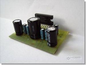
TDA1558Q car power amplifier
TDA1558Q is a monolithic integrated class-B output amplifier in a 17-lead single-in-line (SIL) plastic power package. The device contains 4 x 11 W single-ended or 2 x 22 W BTL amplifiers and has been primarily developed for car

- Requires very few external components
- Flexibility in use Quad single-ended or stereo BTL
- High output power
- Low offset voltage at output (important for BTL)
- Fixed gain, Good ripple rejection
- Mute/stand-by switch, Load dump protection
- AC and DC short-circuit-safe to ground and VP
- Thermally protected, Reverse polarity safe
- Capability to handle high energy on outputs (VP = 0)
- Protected against electrostatic discharge
- No switch-on/switch-off plop
- Flexible leads, Low thermal resistance
- Identical inputs (inverting and non-inverting)
source hobbielektronika.hu 4-Channel Car Amplifier Circuit TDA1558Q schematic pcb files alternative link:
Password: 320volt.com
Published: 2009/12/01 Tags: audio amplifier circuits, ic amplifier
PCB Using Laser Toner Transfer Ironing Printed Circuit Board
Earlier laser printer PCB output took coated paper and supplied with the printed circuit board in preparing Yucel Basic brother’s prepared a letter (Iron and Easy Printing Circuit Board (PCB) Preparation) I shared where you can watch videos or still with the same method of printed circuit boards is preparing process how to do video better You can understand
Initially suitably cut to the size of the drawing pcb copper plaque (phenolic) are heated with iron on a4 paper konulup whereby a short-term plaque toner transferred by ironing.
Ironing PCB Using Laser Toner