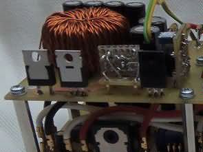
Adjustable Laboratory power supply adjustable Voltage 0-30v adjustable current 20Ma-5A TL494 DC-DC Buck Converter high efficiency.
A PWM generator is used to generate budiaceho signal for spínanú control. As a source of PWM the signal is used, the integrated circuit TL494 PWM signal for switching of the upper trigger is created using the outputs C2 and E2. The collector (C2) is connected to 5V power supply, which is in introduced to the emitter (E2). For the regulation of the striedy PWM chip TL494 is used to input the DTC (Death Time Control) which is with control voltage from 0 to 3.3 V, making it jump regulation from 3% to 100%. This is rebound, not striedy, which means that the maximum output alternates is 97% in zero voltage at the entrance of the LIBRARY.
0-30V 5A Laboratory power supply Circuit TL494 DC DC


This problem is resolved in formed rezistor R3, R5, R6 and IC1B. As a reference for reading is used a source of reference voltage linear regulation. The reference voltage is inverted by the operational amplifier IC1A. From this entry is input Control, which is connected directly from the input linear regulation, which from a regulatory voltage 0-30 In voltage of 3.3-0 V. Output frequency is given by the value of C1 and R7


![]() Lab power supply circuit pcb schematic all files alternative links:
Lab power supply circuit pcb schematic all files alternative links:
FILE DOWNLOAD LINK LIST (in TXT format): LINKS-25604.zip
Published: 2016/06/08 Tags: power electronic projects, power supply circuit, power supply project, tl494 circuit
800W Class D Amplifier Circuit IR2110 PWM
2X400W Class D Amplifier Project with IR2110 . The function of the PWM modulator For clarity of explanation of the function of the entire PWM modulator it is advisable to split it into a few blocks away. The first and most important block is the generator of triangular signal, which consists of the integrator formed by the operational amplifier THS4271
Schalt Labornetzteil 0-30V 5A TL494 Abwärtswandler
Einstellbare Labor Stromversorgung einstellbare Spannung von 0-30v einstellbar Strom 20Ma-5A TL494 DC-DC-Abwärtsregler mit hohem Wirkungsgrad.
Einen PWM-generator wird verwendet, um generieren budiaceho signal für Kontrolle. Als Quelle der PWM das signal verwendet wird, wird der integrierte Schaltkreis TL494 PWM-signal für die Umschaltung auf den oberen trigger erzeugt werden, indem die Ausgänge C2 und E2. Der Kollektor (C2) angeschlossen ist, 5V-Netzteil, das ist in der eingeführt, um den emitter (E2). Für die Regelung der striedy PWM-chip TL494 verwendet wird zur Eingabe des DTC (Tod-Zeit-Kontrolle), die mit Steuerspannung von 0 bis 3,3 V, so dass es springen Verordnung von 3% bis 100%. Das ist Erholung, nicht striedy, was bedeutet, dass die maximale Leistung Stellvertreter ist 97% in der null-Spannung am Eingang der BIBLIOTHEK.