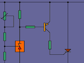
The construction of the mentioned protection against overvoltage me besides the fact that most electronic components (active semiconductor components) is too high supply voltage is destroyed. Therefore Safety expensive electronic system or apparatus is therefore to protect against power surges, no unnecessary luxury. A prerequisite for the effectiveness of such protection is the speed of response. It does not make sense use a surge protector with a slow relays to disconnect power surges, because it’s long too late when we relay drops out. Therefore, for protection against surges thyristor TIC126 is used, which is much faster than conventional relay. If the surge and the thyristor lights and shorts the supply voltage. This has connected device is protected. As a result of a short circuit is melted fuse F1 and interrupts power supply. Threshold voltage can be set by the potentiometer P1 between 5V and 25V 5A.
Surge Protection Schematic Diagram

First, you need to replace the fuse wire bridge that when constantly adjusting not destroy the fuse. After that set the potentiometer P1 on maximum resistance value (the highest threshold voltage). connect with the controllable voltage source and set the current limit to 1A. The source Set the required voltage value at which there will be the protector. It also monitors the current limit to controllable resource and also turn the potentiometer P1 until such time as will activate the current limit. This completes the setting. Remove the wire bridge over the fuse and it will be filled fuse in the range 0 – 5A. After the device is ready for use.
Surge Protection Circuit PCB schematic files download:
FILE DOWNLOAD LINK LIST (in TXT format): LINKS-25352.zip
Published: 2012/07/04 Tags: power electronic projects
Applause Acoustic Lamp Switch Circuit
Acoustic Switch circuit CD4011 CD4001 Cmos circuits based on supply voltage 12 volts dc according to the sound received through the integrated circuit output depending on cd4001 mikorofon relay works. With the relay contacts in the lamp circuit, the author attached to the running lamp relay is connected to the circuit output that applause. Sound sensitivity can be adjusted with potentiometer P1 100 k on the circuit.