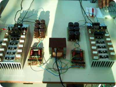
System 500W RMS at 4 ohm 620W RMS power gives 2Ω, 4Ω 500W RMS, 8Ω 380W RMS Circuit of the original scheme 8 MOSFETs used and 4Ω 400W writes 2Ω speakers in order to work 10 mosfet I used the original transistors toshiba 2SK1530 and 2SJ201 but the price is expensive to have found IRFP240 and IRFP9240 have used the results are obvious works perfectly.
Warming normal or even slightly cooler in long-term studies sufficient for the circuit printed circuit board myself drew not cite what I ölçd if I have written her in an open field with two 1600W 8Ω estra cabin for 1 h with’ve tried so far professional systems aratmadı attempt pictures no wish pulls’m some but again another time balls I put
500W Mosfet Amplifier Project


In the supply circuit 6 amp diode 8’ve used very comfortable in use heat very little room for a long time if it works kondasat they 10000mf and small parasites block capacitor formed in the parasites to avoid as well in front of each (wound) 100nF I use (rolled Use lentils passive can stay)
Used ferrite core winding of important diyl but the two windings have to be equal a thick wire necessary to use (current terms) of ferrite core clean mains voltage supplied in the environment have no effect, but the plus and minus voltage equal diyl or noise comes as transformer induced voltage steadies aim departure clean and to achieve stable voltage circuit is used in most power suplly and there in almost all the baggage amp.
RMS 500W Amplifier Circuit proteus ares pcb file: author: X-FI
Password: 320volt.com
Published: 2008/02/24 Tags: audio amplifier circuits, transistor amplifier
TDA1562Q Car Amplifier Circuit
I tested a working amplifier circuit TDA1562Q made with two pieces of the price a little expensive (8 .10 YTL vicinity), but the performance is pretty good, stereo want to use
Car Amplifier circuit wiring diagram TDA1562Q
RMS 500W Verstärkerschaltung
System 500W RMS bei 4 Ohm 620W RMS Leistung ergibt 2Ω, 4Ω 500W RMS, 8Ω 380W RMS Schaltung des ursprünglichen Schemas 8 verwendete MOSFETs und 4Ω 400W schreibt 2Ω Lautsprecher, um 10 mosfet zu arbeiten Ich habe die ursprünglichen Transistoren verwendet, um 2SK1530 und 2SJ201 aber die Preis ist teuer gefunden zu haben, IRFP240 und IRFP9240 verwendet haben, die Ergebnisse sind offensichtlich funktioniert perfekt.
Erwärmung normal oder sogar etwas kühler in Langzeitstudien, die ausreichen, um die Leiterplatte selbst zu zeichnen, zitierte nicht, was ich ölçd, wenn ich sie in einem offenen Feld mit zwei 1600W 8Ω-Estra-Kabinen für 1 Stunde mit bisher professionellem Versuch geschrieben habe systeme aratmadı versuch bilder keine wünsche zu ziehen bin doch mal wieder ein bällchen was ich stelle
500W Mosfet Verstärker Projekt
In der Versorgungsschaltung 6 Ampere Diode 8 haben sehr angenehm in Gebrauch Wärme sehr wenig Raum für eine lange Zeit, wenn es funktioniert, kondasat sie 10000mf und kleine Parasiten Blockkondensator in den Parasiten gebildet, um auch vor jeder (Wunde) 100nF zu vermeiden Ich benutze (gerollt Linsen passiv verwenden kann bleiben)
Verwendete Ferritkernwicklungen aus wichtigem Diyl, wobei die beiden Wicklungen gleich dick sein müssen, um die in der Umgebung zugeführte (aktuelle Bezeichnung) saubere Ferritkern-Netzspannung zu verwenden, haben keine Auswirkung, jedoch kommt die Plus- und Minusspannung gleich Diyl oder Rauschen als transformatorinduzierte spannungsstetigkeiten zielen abgang sauber ab und um einen stabilen spannungskreislauf zu erreichen wird in den meisten stromversorgungen und dort in fast allen gepäckverstärkern eingesetzt.