This project uses the 12F675, it was chosen because of its low cost, A/D convertor and flash memory. This security system was designed to be used in a simple installation with just a hidden switch and not a keyboard. There are several features such as a battery monitor built into the code that also make it good for remote locations just run off a battery. Also all the delays and and other parameters are put into flash memory just by using a visual basic program and the serial port of a PC.
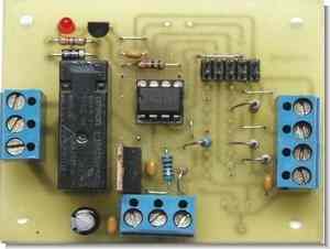
As you can see in the photo there are unused holes in the board, the board was designed for several different variations and future applications. Also the picture shows a optional header. This header connects to a switch on my programmer so that I flip the switch to “load” press the program button then switch to “run”. If I need to change the program all I need to do is flip the switch to “load” press the program button then switch to “run”, no need to unplug the IC or anything.If the header is to be used the 4 thin traces between the header need to be cut. The ground trace remains intact.
PC Programmable Security System
The Schematic

Parts list
R1,R6 1K ohm .25W resistor 5% LED1 3 mm LED
R2 2K ohm .25W resistor 1% C1,C3,C4,C5 0.1 ufd capacitor
R3 1K ohm .25W resistor 1% C2 33 ufd 25 V electrolytic capacitor
R4,R5 10K ohm .25W resistor 5% Q1 2N3904 transistor
R7 470 ohm .25W resistor 5% K1 G6RN-1 relay
TB2 4 Pos Terminal Strip IC1 PIC12F675
TB1,TB3 3 Pos Terminal Strip IC2 LM340T5
10 Pin Header
The PCB

The Program
As mentioned above the delays and parameters can be programmed in anytime by the use of a visual basic program and the serial port on a PC. All you need to do is:
– start the VB program.
– connect the PC’s com port TX out pin to the Serial In on TB1 and PC’s com port ground pin to the ground on TB1
– select the correct Com port on the VB program and press Set Defaults.
– change any parameters
– connect 9 to 12 volts to TB1
– within 10 seconds of above press “Upload to Pic” , the program puts the PIC in program mode for only 10 seconds at power up
You can download this visual basic program here
What the above parameters are
Entrance delay – the time you have to disarm the system with the hidden switch after the door switch is opened.
Exit Delay – the time you have to arm the system with the hidden switch and close the door.
Siren Timeout – the length of time the relay is activated after a alarm.
# of chirps ARMED – you may adjust the number of chirps that you get after a exit delay to confirm the system is armed. Enter 0 is you want none.
# of chirps TRIPPED – if the system has been tripped and after the siren timeout when disarm the system you you may adjust the number of chirps that you get. Enter 0 is you want none.
# of chirps LOW BATT- you may adjust the number of chirps that you get when a low battery condition is detected. Enter 0 is you want none.
Chirp time off – you can set the on/off ratio of the chirp here.
Chirp time on – you can set the on/off ratio of the chirp here.
Low Bat Chirp Int – you can set the interval that the low battery chirp comes on.
Low Battery – the level in tenths of a volt that will indicate a low battery ie 110 is 11.0 volts
Spare – not used
Spare – not used
The code here was not optimized, may not be the most efficient and not nicely laid out but it works real good.

Password: 320volt.com
Published: 2008/02/10 Tags: microchip projects, microcontroller projects, picbasic pro examples
220V Isolated Light Flasher Circuit
In working with flasher circuit 220v 100w power frequency and duty cycle can be setup to 220v ac lamp with a high-powered flashers can
6 .12 volt supply voltage integrated circuit LM555 Timer is based on the isolation Optokubl MOC3021 triac driver used for load control TRIAC used in the frequency range 1 Hz … 5 Hz TIC22
220 lamp flasher circuit
Dieses Projekt verwendet den 12F675, der aufgrund seiner geringen Kosten, des A / D-Wandlers und des Flash-Speichers ausgewählt wurde. Dieses Sicherheitssystem wurde entwickelt, um in einer einfachen Installation mit nur einem versteckten Schalter und keiner Tastatur verwendet zu werden. Der Code enthält mehrere Funktionen, z. B. einen Batteriemonitor, der auch für entfernte Standorte geeignet ist, bei denen nur die Batterie leer ist. Auch alle Verzögerungen und andere Parameter werden mit einem Visual Basic-Programm und der seriellen Schnittstelle eines PCs in den Flash-Speicher geschrieben.
Wie Sie auf dem Foto sehen können, befinden sich unbenutzte Löcher in der Platine. Die Platine wurde für verschiedene Variationen und zukünftige Anwendungen entwickelt. Das Bild zeigt auch einen optionalen Header. Dieser Header ist mit einem Schalter an meinem Programmiergerät verbunden, sodass ich den Schalter auf “Laden” stelle, die Programmiertaste drücke und dann auf “Ausführen” stelle. Wenn ich das Programm ändern muss, muss ich nur den Schalter auf „Laden“ stellen, die Programmtaste drücken und dann auf „Ausführen“ umschalten. Der IC muss nicht ausgesteckt werden Spuren zwischen dem Header müssen geschnitten werden. Die Bodenspur bleibt erhalten.