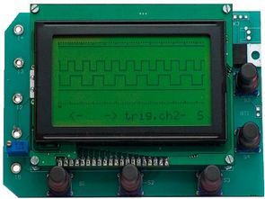
Pic18f4580 microcontroller circuit based on logic analyzer display 128 × 64 graphic LCD (GLCD to DEM128064-FGH-PW) used. Prepared by the assembly source software. Asm,. Hex file and PCB’s.
Logic analyzer circuit characteristics;
Sampling Frequency: 200Hz, 2MHz
Number of Channels: 4 pcs
Memory per channel in 1024
Trigger levels (Trigger Level): + And on and on-and
Supply: 12volt + 9V battery
9-volt battery used in the circuit will be charged automatically on the circuit’s charging section
Source: http://www.rlocman.ru/shem/schematics.html?di=64291 USB Analyzer Circuit files alternative link :
FILE DOWNLOAD LINK LIST (in TXT format): LINKS-10317.zip
Published: 2010/05/16 Tags: microchip projects, microcontroller projects
Framework for USB PIC18F4550 Generic HID VisualStudio
PIC18F series microcontrollers with USB port USB HID Framework applications can be developed for the open source implementation of the example circuit (USB LCD text transmission) and Visual Studio’s C # source code
USB Generic HID PIC18F4550