PIC18F4550 controller installed on the computer (USB) connection for robotics and automation projects an advanced control card required summer, bill of materials, schematics, PCB drawings and other documents are prepared for students of mechatronics circuit (suboard)
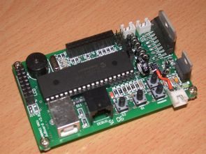
Sabanci University General Purpose Microcontroller Board II (AKA SUBOARDII) is a compact board designed around a Microchip PIC18F4550 controller for two purposes: Introducing new mechatronics students to microcomputers and to be used as a low level controller for robotics and automation projects.
The design principle was to make it as simple as possible to use while providing most of the common functionality required for average student or professional project, and at the same time have a low cost and repairable system. Motors and display can simply be plugged in and used directly without building additional circuitry which is advantageous, while it is possible to extend the functions, if necessary, through an expansion connector.
SUBOARDII was designed and built by Undergraduate student Ender Kazan and Mechatronics faculty member Ahmet Onat during the summer of 2006. PCB design was done using EAGLE graphic layout editor, and two layer PCBs through hole PCBs were sent to a local manufacturer. The design incorporates surface mount packages for most components to save space, but a DIP package for the CPU to facilitate easy replacement.
SUBOARDII Properties:
One of its main features is that it has a USB port which can be used for two purposes:
1. Connection to a PC, like a general USB peripheral.
2. To program it from the PC by downloading your code.
Which type of peripheral it appears to the PC is programmable by the user. It can be used for such diverse purposes as data acquisition and motor control to special human interface devices (such as inertially controlled USB mouse for example). High speed transfers are supported. USB applications require thet the user write a program for both the PC and for SUBOARDII. Examples and a USB programming framework are available through Microchip. The board can also bepowered by the USB bus.
A resident firmware on the microcontroller can be used to boot it into download mode in which the user can download his program to SUBOARDII flash memory through the USB connection. The RAM area where the download firmware resides can be independently write protected to prevent it from being accidentally overwritten. This provides a very convenient and fast method of program development. For those who wish to use the conventional method, the standard Microchip debug connector is also provided.
Another feature is the on-board dual H bridge motor driver which allows PWM drive of two small DC motors up to 2A current draw each or one stepper motor. A connector is also provided that can emulate a quadrature decoder through software. Therefore, servo control of one motor with reference from the PC is possible. Motor power can either be taken from the board power or separately, up to 30V, by a solder jumper at the back of the board.
User interface of SUBOARDII is up-to-date thanks to the on-board LCD connector to which a common Hitachi 44780 based LCD alphanumeric display with backlight can be directly attached. Further, three free switches two LEDs and a piezo beeper can also be used in a similar manner. A free potentiometer attached to an ADC port can be used as an adjustment. Since some LCDs on the market have the supply pins reversed, there are solder jumpers on SUBOARDII to accomodate both types.
There are 13 channel 10 bit ADCs, 2 10 bitPWM outputs, 4 timers, EAUSART, more then 30 general purpose inputs and outputs, 32KB of program memory, 2048 Bytes of RAM memory available on the PIC 18F4550. The processor runs at 48MHZ. Internal PLL can be used to change the clock speed by software. It is also possible to have a backup oscillator for safety critical applications in case the main oscillator fails.
Since novice users are in the audience of SUBOARDII, protection circuitry was also added. There is reverse voltage protection on both supply inputs. The I/O ports of the CPU on the expansion connector are also protected from shorts to ground or Vcc through series resistors. The ports can still be used to drive the usual loads by taking the protection resistance into the calculations for high power loads such as LED, or by simply ignoring it for high input impedance loads such as transistors.
The board can be used as standalone, USB bus powered or both. Due to the limitation in the USB specification, up to 100mA can be drawn at startup, which may be increased to 500mA during initialization after negotiating with the host.
Programs can be written in several ways. For the complete novice, one good language is PIC_BASIC_PRO. It is quite simple to write programs but does not provide for multitasking, good control of interrupts or all hardware features of the CPU.
A more advanced option is to use Microchip C18 ‘C’ compiler. This can be used as a lower level language and allows the user to write speed optimized code, while allowing for more complex programming tools. Finally SUBOARDII can be programmed using Microchip assembly, PASM. This is the lowest level and gives the highest control, but difficult to write high level programs. All three languages are supported by Microchip’s graphical development environment MPLAB.
PIC18F4550 Robot Control Board


DC and Servo Motors and LCD Display can simply be plugged in and used directly without building additional circuitry source : fens.sabanciuniv.edu/suboard Robot Control Board circuit files Alternative link:
Password: 320volt.com
Published: 2010/04/23 Tags: microchip projects, microcontroller projects
CCS C Examples PIC18F2550 USB LEDs
Two main application’s source code ccs c there are other files necessary computer programs. One of the applications PIC18F2550 USB LED turn off the LEDs are doing has a source code through Visual C #. If other applications ACD `toggle LEDs also are also studying the source code of computer software, but I guess I’m not sure which program prepared by written with asamb
Applications can build on border bred to run, or you can use the test circuits, or you can set up the following circuit schematic drawings in this way is useful for beginners