A useful test development circuit for the PIC18F2550 popular in the PIC18 Series. Lcd and Glcd tests can be done. There are 6 channels 10 adc. There is a usb connection and an additional power supply input. The diagram, pcb, parts list and sample application are shared with the test software.
PIC18F2550 development board Hardware;
The microcontroller is a 28 pin PIC18F2550, which can be used with an optional external crystal. We can use internal oscillator. The software installer uses only three pins, PGD, PGC and MCLR. J1 is for ICSP, we can connect it to application clipboard for both code loading and execution. User I/O ports are 6-channel analog input RA0-RA5. PORTB is for RB0-RB7 LCD interface. User can select LCD on JR1 connector or GLCD on JF1 connector.
PORTC is used to interface RC0-RC2, LTC2400 / LTC2420 SPI bus, sigma delta converter. RC4 and RC5 are USB port signal. RC6 is also available in J2. RC7 is the debug LED. D2 protects VCC from high voltage programming on the MCLR pin. U2 can be 20 bit or 24 bit resolution, sigma-delta converter, LTC2420 or LTC2400. J3 is a bridge to choose 50Hz or 60Hz rejection of common mode noise frequency. The reference voltage is +2.5V U3 generated by the LM336. It can be powered by the rechargeable battery BT1.
Sample Code: LTC2400 Interface
The example c program demonstrates interfacing with the sigma-delta converter LTC2400. MCU uses 4MHz Xtal with HS oscillator, no partitioning option. The program reads 24-bit data from the LTC2400, performs digital filtering and displays the input voltage in units of 0.1uV.
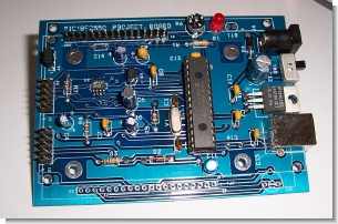
The new PIC18F2550 Project Board was designed as the development platform for student projects.
The board features
MCU: PIC18F2550 with external xtal,
ADC: one channel 0-2.5V sigma-delta converter, Linear Technology LTC2400/LTC2420,
6-channal 10-bit ADC 0-5V,
Display: Two connectors for text LCD or GLCD,
USB: onchip USB port with type B connector,
Power supply: onboard low dropout regulator, rechargeable battery,
Code programming: 10-pin header for In Circuit Loader.
Password: 320volt.com
Published: 2009/11/02 Tags: microchip projects, microcontroller projects, pic18f2550 projects
PIC18F2550 Projects Test and Development Board
PIC18F2550 PIC18 series are popular in handy for a trial modification circuit. LCD and GLCD tests done 6-channel ADCs 10’s USB connection and has an additional power supply input schema, PCB, parts list and shared with the sample application testing software