LM2940 is used for MC34063 pic 16ff88 for supply voltage 12v dc led supply of tacho meter circuit. Dual Display LED Tachometer A sensitive and accurate tachometer is essential for car enthusiasts. This unit has a bright 4-digit display and a 32-color circular led display. The LED indicator graphic responds quickly to changes in RPM, while the digital display shows accurate RPM readings with a continuous throttle.
Digital tachometers may be measuring accurately, but they do not respond like an analog instrument. This tachometer circuit combines the best features of analog and digital devices: engage the throttle and the LED bar graph will quickly respond to the change in engine speed, while the true RPM will be displayed on a 4-digit display up to 1 RPM resolution.
Gear shift light and rev limiter output are standard features and can work with almost any car or motorcycle (except magneto ignition). A wide variety of optional settings make this tachometer a versatile tool. For performance cars and motorcycles, the versatility is to keep the engine revs up to 10,000rpm.
Tachometer Circuit Block Diagram

The circular gauge section of the tachometer is made as small as in practice and can be fitted to the instrument cluster of your vehicle if there is enough space. Alternatively, it can be placed in a cylindrical box and mounted using a suitable holder on the instrument panel, windshield or instrument panel. The main electronics of the tachometer need to be mounted under the instrument panel (or inside the side cover on a motorcycle).
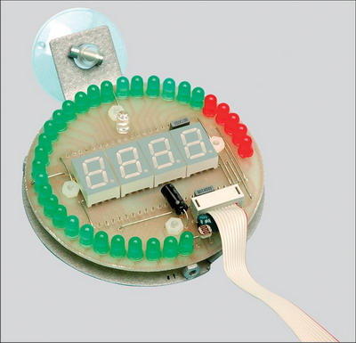
The LED bar graph is arranged in a circle with a diameter of 76 mm, covering the range of 286 °. Most of the 32 LEDs are green except for the extreme clockwise ones, which use five red LEDs to indicate “red line” RPM. You can increase the “red line” indicator up to 10 LEDs.
The number of red line RPM and red line LEDs can be selected during calibration. The speedometer then automatically calculates the RPM increments needed to light each LED.

Source: http://www.siliconchip.com.au/cms/A_107675/article.html
Tachometer Circuit schematic PCB PIC16F88 pic assembly source code files alternative link:
Password: 320volt.com
Published: 2008/09/04 Tags: microchip projects, microcontroller projects, pic assembly example, pic16f88 projects
TL494 12V Flourescent Lamp Inverter Circuit L6574 Ballast Driver
Reasons for these, fluorescent lighting is the natural choice in commercial and retail buildings, workshops and factories. For battery-powered lighting, fluorescent lights are also the first choice because of their high efficiency.
CAUTION Be careful is working with high voltage capacitor circuit connections Beware + – If you connect the high voltage polarity may be large explosions before running the insured Power Line circuit, protective goggles