The PIC16F877 microcontroller, prepared with activated an old ISA ethernet (3com eherl Link) Used guess PIC internet connection with an application I’m not sure 🙂 circuit aim could not understand the pic programming dealing with people who can solve resource asebbely asm PCBs (eagle) control program and so on. most likely reason for not publishing files to the work of people who are interested will work.
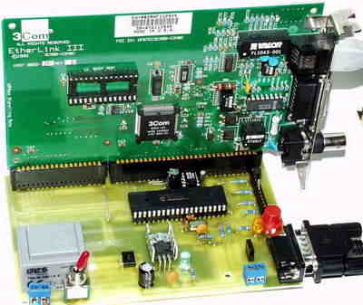
ISA Ethernet PICmicro Microcontroller Web Server

DC from 7 to 20V connected to X1, or if You set the transformator 230V/AC (in Europe) connected to X3 (manupulation with 110/230V may be dangerous, so be carefull with it – it is Your responsibility to do it save, according to the appropriate security rules, not mine!)
Pic3Com source code Pic3Com_001.zip (in Microchip assembler format) There are some defaults – IP, APRS strings in the EEPROM, do not forget to change them to Your needs.
HEX assembled program for PIC 16F877 and 20MHz crystal There are some defaults – IP, APRS strings in the EEPROM, do not forget to change them to Your needs.
I have made Pic3Com construction (version 0.1) with idea to have a basement for PIC16F877 and Ethernet (with TCP/IP protocol) cooperation. I have choosen ISA NIC 3C509 (my favourite ethernet card) for this project, because ISA protocol is simple to implement in microprocessors.
– Version 0.1 implements:
inicialization of ISA 3c509 (3c509B) NIC – NIC have to be configured for communication I/O=0x300 and Interrupt 10
address resolution protocol – ARP
internet protocol – IP (support for default gateway included for Internet communication)
ping (ICMP Echo Request / Reply)
TCP protocols – TELNET (server and client) and HTTP (server, 2KB of PIC’s RAM are dedicated for html pages)
UDP protocol daytime – for synchronization of internal DS1302 RTC
temperature measurement (up to 7) connected SMT 160-30 sensors (as a reply to appropriate Telnet protocol based request)
connect to aprsd stream with possibility to authorize and send data tracked from connected meteostation
two switchable aprsd data output formats (TNC2 or UIView log)
multilevel program run debug possibility
control via RS-232 port
configuration via processor’s EEPROM
There remains (in version 0.1) for about 2KB free program memory (or 1.5KB if maximal debug level choosen) for other functions implementation
The source code is fully commented for theese which wants to use it or change for non-commercial aplications. Use for non-profit/non-commercial application is allowed and free of charge.
After power-on LED should flash twice shortly followed by one longer flash – it indicates that 3c509 NIC initialization was successfull. After that program enters main loop and waits for data from the Internet (Telnet or Http) or for data from meteostation, PC, … connected to RS-232 port. If it is required by configuratin it asks gateway for MAC address, sends Udp request for RTC synchronization or connects itself to configured aprsd server, sends autorization, data from meteostation,… all is based on EEPROM configuration
If ARP request for Pic3Com’s IP is received, it is processed and reply is sent
If ICMP ping (Echo Request) is received, Echo Reply is sent. Notice that only first 222 bytes of Ethernet frame is readed by PIC. This is valid for any network communication, so for ping it means that max 180 data bytes of ping packet is readed and returned back!
For TCP sessions program sends max segment size (MSS) option in TCP negotiation – for Telnet protocol MSS is reduced to fit the whole Ethernet frame into 222 bytes. For http protocol large MSS (about 65000 bytes) is used to enable http client to send whole HTTP GET request without need to split it into parts. Because PIC answers only first HTTP GET packet which starts with GET clause.
In case that session with aprsd server is disconnected, program will start sending connect requests (after timeout) to recover connection.
Time synchronization via daytime/udp protocol is repeated every aprox. 2 hours to be sure that internal RTC is accurate. If You want to use this feature You have to enable this service on some server in the Internet. You can choose any UDP port for daytime, because port for daytime is taken from the processor’s EEPROM configuration. I recommend not to use default udp port 13, but some port above 1024.
If Http request is received (it is TCP/IP packet with port 80) (or 14501 for aprs http) program checks the first letter of requested page and returned the page if found in html page area of program memory. If the corresponding page is not found, program returns default index page.
If Telnet request is received (port 23) program returns prompt and waits for commands. Every packet is commited by prompt. At this moment only 2 commands are implemented: q = quit (ends telnet session) and remote reset of program – this feature have to be enabled in compilation time.
If Telnet request for SMT port (18624) is received program checks from configuration where SMT sensors are connected and measures it’t temperature values. Finaly returns Timestamp (from RTC if one is connected) followed by temparature values (in Celsius) from SMT’s. And telnet session is disconnected by program.
Program listens on the RS-232 port too and all commands send via this port are processed. (Data from connected meteostatin is command too – with meaning: save following data as WX string int RAM registers.)
For the first power-on initialization of DS1302 RTC in EEPROM should be enabled. You can disable this if RTC is backupped by the capacitor. If capacitor discharge, You have to reenable initialization too. If RTC is not initialized it may not work properly.
If 3c509 is not recognized by program, LED will be flushing quickly and program stops at this point. Check if NIC is well placed in the socked and if is functional (in some PC…).
If NIC is found but is not propperly configured for I/O=0x300, LED will be repeatly flushing twice with longer pause between these two flushes. Set up the NIC for I/O=0x300, INT=10, Media=TP. Pic3Com does not support other media type, only TP is supported. If You have NIC (3c509B) with PNP possibility disable PNP function.
There are files with html pages in source zip file including it’s html templates and program for convert html files to the files with RETLW sequencies used in PIC program memory. Bytes with 0x1A value in w*.htm are the ones which are replacet with data dynamickly received from the weather station.
Configuration
For download EEPROM contents and upload back into processor’s EEPROM use of Piceerw program by Petr OK1MAB is recomended (for Windows platform). It uses 9k6, 8N1 communication parametres full installlation 1.4MB; exe only, needs ocx libraries (36kB)).
I will write P3C_CFG program (hope during January or February) for easy editting of Processor’s EEPROM (changing configuration).
For now You must edit downloaded EEPROM configuration in some hexadecimal editor. What byte means what is described at the end of Pic3Com source code. NOTICE – the very first byte from EEPROM is not stored in file, so bytes in file are shifted by one (byte on address 0x00 in file is from address 0x01 in EEPROM)
RS-232 commands description
Following commands are implemented ( ^ represents keyboard button ESC, character Escape 0x1b)
^D – write following bytes into EEPROM (I do not advice you to use it by hand :-))
^U – reads configuration from EEPROM, first byte returned is data size, (255 for this module) followed by EEPROM bytes from address 0x01 to 0xff
^R – display PIC registers content – binary
^r – display PIC registers content – in ASCII format
^W – display PIC WX registers content – string received from meteostatin
^w – write following bytes as WS string into registers – (meteostatin sends this string starting with ^w) format is
^T – display the time from RTC
^t – set RTC time to the following string – string format is
^O – set RS-232 aprs output data format (if the next character is U, format is UIView log, other character means TNC2 format)
^V – display firmware version
PIC16F877 Web Server Microchip assembler source code schematic pcb files alternative link
Password: 320volt.com
Published: 2008/08/02 Tags: microchip projects, microcontroller projects, pic assembly example, pic16f877 projects
Symmetric Output Audio Amp SMPS Circuit with IR2153 ETD34
I made a simple SMPS with IR2153 before the Transformer EI33 more advanced and powerful but this practice was used transformer (ETD34) you have to wrap transformer circuits, I applied my computer was disconnected from the power supply circuit
It also has ir2153 overcurrent ir2153 protection section of the primary measurements are made using a small ring cores (current transformer) shared all the details of calculation, etc. oscilloscope measurements. In the sprint circuit layout has been prepared by the detail and file to pcb file
If you pay attention IR2153 supply for part of my circuit according to a healthier and more powerful mosfet (IRF730) and Zener (BZX85C15), the regulator has sections and on the transformer additional winding rectified supply supplemented circuit 2 × 40volt output is giving 230 .300 w power between there
IR2153 Circuit