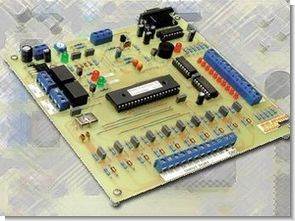
I/O Control analog sampler PLC system circuit is based on PIC16f877, ULN2003 is used in the outputs, and PC serial RS232 connection is provided with MAX232 integration. 32 bit windows control program schema pcb other drawings and .hex .bas source files are available
Serial I/O Controller and Analog Sampler
It connects to your PC’s serial port and can switch relays based on voltage, resistance, temperature and digital inputs. It also includes system timers and can be operated as a PLC style controller.
PC-based serial I/O controllers and analog samplers are hardly new. However, this 10-bit unit has some special features that are normally hard to find in a DIY projects, including closed-loop control (as in a thermostat), spreadsheet logging, programmable I/O logic control, and temperature and light. In addition, the detection includes real-time system timers that can be used to control two built-in relays.
PIC16F877 I/O Project


Speaking of relays, you can also define “less than” or “greater than” values in the software to control them. This can be done for any of the input variables such as temperature, LDR resistance, analog voltage inputs, and digital inputs.
For example, you can set one of the relays to turn on if the temperature rises above 20°C and this can then control a fan or other equipment. In short, there are many possibilities, especially since the unit can be directly interfaced with other CMOS circuits.
The microcontroller used for the project is PIC16F877 with 8K flash memory, 256 bytes of RAM, eight analog inputs, 256 bytes of EEPROM memory and many other features.
General characteristics of the circuit
10-bit digital input port (0-16 volts)
0-5 volt and 0-25 volt analog inputs
Temperature and light sensing (ldr) inputs
High current 10-bit digital output port
Closed loop control using two relays
Serial interface (2400 bit/s, inverted)
Temperature accuracy: +- 1c
Built-in system timers plus buzzer
32-bit Windows-based software
Fully functional spreadsheet recorder
CRO style analog chart plotter
Combination I/O “and or” logic
Source: http://www.siliconchip.com.au/cms/A_105433/article.html
PIC16F877 Series I/O Circuit Analog Control schematic pcb source code alternative links:
Password: 320volt.com
Published: 2009/02/08 Tags: microchip projects, microcontroller projects, pic assembly example, pic16f877 projects
Simple Logic Probe Circuit with LED Indicator Level Measurement CD4001
Simple Logic Probe Logic level measurement for cd4001 (cmos nor) designed with a simple measuring circuit 6v works with two 3v cr2032 (pc motherboard bios is known as battery) on top of each other and can be used with serial connection such as you see in the picture below if you use a wide heat shrinkable tubing is not wrong with you or even boxing smd materials are moved to the back with a critical piece of the pcb is designed to easily destroy all materials can be found.
Logic Probe Project