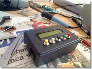
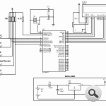
This circuit using a PIC 16F877 microcontroller LCD (Liquid Crystal Display) application was made on the stopwatch and countdown. Counting the TMR0 interrupt for the microcontroller is used. For circuit design and printed circuit board operations and Proteus ISIS Proteus ARES program is used. Flow diagram of the circuit is as follows.
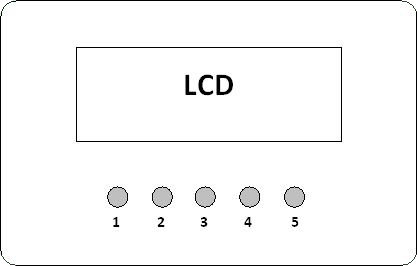
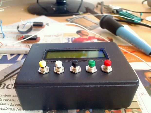
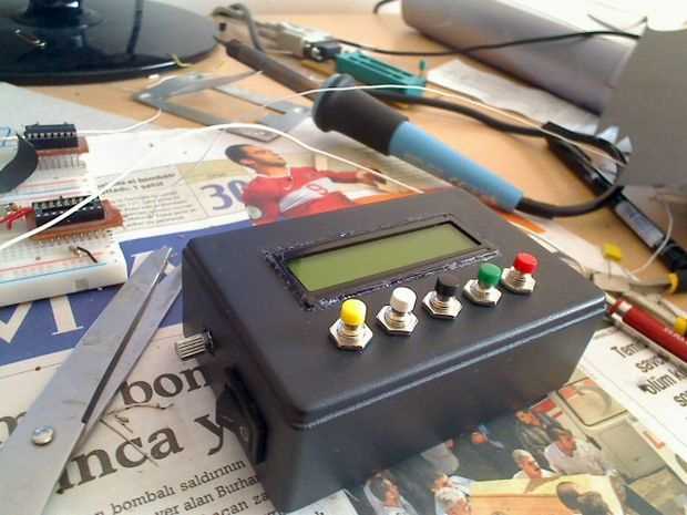
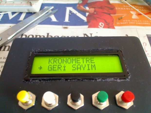
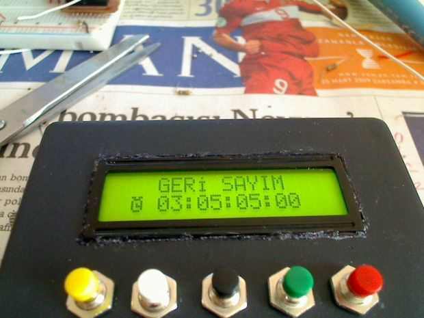
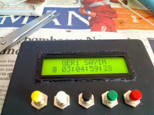
Countdown Counter Circuit Front Panel
1: to move up in the menu and increase the value of the countdown timer button,
2: to move down the menu button and countdown timer reduction in the value,
3: confirm the selected menu button,
4: Stopwatch and countdown timer for the Start / Stop / Resume button,
5: Stopwatch and countdown timer countdown timer is reset and the hour, minute, second values to be selected,
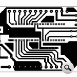
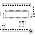
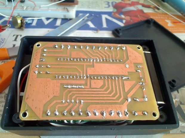
LCD Stopwatch Circuit Diagrams and PCB
PIC16F877 with LCD stopwatch and countdown counter all the files belonging to the isis circuit simulation software ares pcb and source files PicBasic pro files
Password: 320volt.com
Published: 2009/04/07 Tags: microchip projects, microcontroller projects, pic16f877 projects, picbasic pro examples
Feedback PWM Motor Control Circuit with PIC16F628 L298
Circuit L298 (bridge-mounted motor drive) and PIC16F628 microcontroller based on the stop, sudden stop, start, improve, finish, forward, rewind controls have brake position the motor generator to the state in case of falling energy battery again sending software in assembly language prepared. Asm. hex and isis proteus. DSN files available
Feedback motor drive circuit
Source files link is not working.
How can the stopwatch be modified to add a relay or opto isolator and solid state relay to close when timer reaches 0?
I checked. no problem