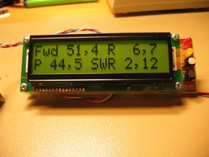
SWR meter circuit pic16f877 microcontroller with lcd display displays the information on a printed circuit board with 2 × 16, schema diagrams in the C source code library files (adc. c, lcd8 c, swrm. c, timers), and I have 2 different hex code for 16f877a 16f877
SWR meter circuit features;
Power range 5-100W
Frequency range of 1-30 MHz
SSB operation for the Peak indicator
Forward, backward, power and SWR representation
Simple two-button interface
SWR warning and alarm LEDs


Source: http://www-diyhome.blogspot.com/ Alternatif link:
FILE DOWNLOAD LINK LIST (in TXT format): LINKS-14229.zip
Published: 2011/03/19 Tags: microchip projects, microcontroller projects, pic16f877 projects
Non-Isolated AC-DC Converter LNK302P Buck Boost LED Power
Non-Isolated Converter circuit mains voltage half wave input voltage available 85v rectification … 265v ac especially suitable for white LEDs run already in practice 12 white led on led run of the circuit performance focused plowed.
The biggest advantage of insulation of the circuit (lnk302p) as shown in the diagram, the lack of mains voltage dez with direct connected transformer is obsolete, but the resistors, capacitors made by using a healthy circuit than 220v circuits regulate
password please
Hello,
password for all files: 320volt.com