Two of the PIC16F877 microcontroller based on harsh economics Robot Barrier lego robot used a lot in part lego robot can be said also tip31, tip32 bridge motor driver with transistors have a more solid thanks to the movable clamping bodies can hold in front. Other robots could be called the robot obstacle seems simple compared to other projects in front of the robot has 2 units of metal such as antenna assembly software with source code and schema files have been prepared.


Barrier Robot
The project concern with the realization of a Lego’s robot, which was built as an application of the Microchip’s PIC 16F877. The robot’s task is to collect a barrel placed in the space around it.
The PIC controls three Lego’s motors and reads the input from three touch sensors and a laser target finder sensor. One touch sensor is used to detect when the barrel is touched; the other two touch sensors are used to determinate the arms position. The target finder sensor works as follow: the barrel is covered with retro-reflecting tape. When it is illuminated by the lasers light the photo diode detect an increment of light and that means that the barrel is individuated.
The robot makes a scan around it (the motors, which controls the robots movement round in different ways) When the barrel is found the robot advance in the barrels direction (both motors round in the same way), until the PIC don’t obtain the information that the barrel is touched throw the touch sensor. Once the barrel is touched the PIC stop the robot and with its mechanical arm pick up the barrel. The arms movement is controlled with the third motor. The barrel is collocated in a space behind the arm. After this the arm goes back to its default position and the robot makes another scan.

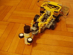
Robot handicap Auto Lug
The robot can be driven by a microcontroller P16F877. It has two switches on the front that can detect obstacles. When struck an obstacle the robot stops, back, turn and continues its march.
The logic of the robot was entrusted to a microcontroller P16F877. The scooter robot are driven through a system of four transistors and two diodes for each motor as a direct link with the microcontroller would have burned the same. All this is powered by a battery.
Source: http://www2.units.it/carrato/didatt/dsp_mcu/relaz_mcu/ Lego Robot Project with PIC16F877 PIC Assembly source code schematic Alternative link:
Password: 320volt.com
Published: 2008/07/26 Tags: microchip projects, microcontroller projects, pic assembly example, pic16f877 projects
Ultrasonic Range Finder Circuit AD605 PIC16F876
Ultrasonic distance measurement, detection circuit pic16f876 microcontroller and ad605 (Dual Low Noise Variable Gain Amplifier singlesupply) integrated circuit diagrams used are C and asm software also Resimlerdede oscilloscope’s measurement. 40kHz ultra sonic transducers used as sensors.