Made with clock and thermometer 16F628 PIC-7 Circuit
Friends, I have realized various clock and thermometer with PIC16F628A circuit I explain below. The temperature sensor used in each of the projects is DS18B20.
Clock Thermometer Circuit-1: In this circuit, the clock signal with cutting method I created. I use the LCD screen as a benchmark. I’ve used as the temperature sensor DS18B20 sensor.

Clock Thermometer Circuit-2: In this circuit, the hour and minute indicator I use 7-segment display. I created again with the clock signal cutting method.

Clock Thermometer Circuit-3: This circuit has Hours-Minutes-Seconds indicator and has been created with 7-segment display. The clock signal is obtained by the cutting method.

Clock Thermometer Circuit-4: This circuit Hours-Minutes-Seconds and 7-segment display with indicators has been created. The clock signal from clock pulses of the clock through an exterior wall or table was prepared. Very true working hours.

Clock Thermometer Circuit-5: This program works with 7 segment LED display. Time information (RTC) DS1302 gets its. Shows seconds. Less shows the temperature.

Clock Thermometer Circuit-6: This program works with 7 segment LED display. Time information is received from the DS1302. Shows seconds. Less shows the temperature. Led blinks with medium cutting method.

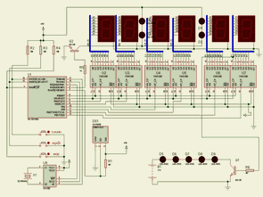
Clock Thermometer Circuit-7: This program works with 7 segment LED display. Time information is received from the DS1302. Shows seconds. Less shows the temperature. Led blinks with medium cutting method. HISTORY shows.

Made with clock and thermometer circuit PIC16F628 7 All source files to the project. Proteus isis simulations PicBasic Pro code:
Password: 320volt.com
Published: 2008/01/12 Tags: microchip projects, microcontroller projects, pic16f628 projects, picbasic pro examples
Electronic Fuse Circuit
Alternatives to Classic Fuse With this circuit can protect the power supply and other devices. If the set current limit is exceeded, or if the output short-circuit protection and to GES. Short-circuit automatically turns off when the current is applied to the circuit.
Circuit voltage of the relay will be equal to the supply voltage. Not just another circuit voltage is 12v can use. Please use 100uF capacitors do. their use voltage to the supply voltage must be appropriate. Please bulamassa BRX46 the circuit thyristor C106 can use it to place.
Electronic Fuse Circuit Schematic Diagram
Uhrenthermometerschaltungen mit PIC16F628 PICBasic Pro
Hergestellt mit Uhr und Thermometer 16F628 PIC-7 Circuit
Freunde, ich habe verschiedene Uhren und Thermometer mit PIC16F628A-Schaltung realisiert, die ich unten erläutere. Der in jedem Projekt verwendete Temperatursensor ist DS18B20.
Clock Thermometer Circuit-1: In dieser Schaltung habe ich das Taktsignal mit Schneidemethode erstellt. Ich benutze den LCD-Bildschirm als Benchmark. Ich habe als Temperatursensor DS18B20 Sensor verwendet.
Uhrenthermometerschaltkreise mit PIC16F628 PICBasic Pro ist für 1 150×150 lcd-termometer ausgelegt
Uhrenthermometer Circuit-2: In dieser Schaltung verwende ich die Stunden- und Minutenanzeige mit einer 7-Segment-Anzeige. Ich habe wieder mit der Taktsignal-Schneidemethode erstellt.
Uhrenthermometer-Schaltkreise mit PIC16F628 PICBasic Pro picbasic Saat Termometer-Anzeige 150×150
Uhrenthermometer Circuit-3: Dieser Schaltkreis hat eine Stunden-Minuten-Sekunden-Anzeige und wurde mit einer 7-Segment-Anzeige erstellt. Das Taktsignal wird durch das Schneideverfahren erhalten.
Uhrenthermometerschaltungen mit PIC16F628 PICBasic Pro pic16f628 uln2004 ds18b20 termometer 150×150
Uhrenthermometer Circuit-4: Diese Schaltung Stunden-Minuten-Sekunden und 7-Segment-Anzeige mit Indikatoren wurde erstellt. Das Taktsignal von Taktimpulsen der Uhr durch eine Außenwand oder einen Tisch wurde hergestellt. Sehr wahre Arbeitszeiten.
Uhrenthermometer Circuit-5: Dieses Programm arbeitet mit einer 7-Segment-LED-Anzeige. Zeitinformation (RTC) DS1302 bekommt seine. Zeigt Sekunden an. Weniger zeigt die Temperatur.
Uhrenthermometer Circuit-6: Dieses Programm arbeitet mit einer 7-Segment-LED-Anzeige. Zeitinformationen werden vom DS1302 empfangen. Zeigt Sekunden an. Weniger zeigt die Temperatur. LED blinkt bei mittlerer Schneidemethode.
Uhrenthermometer Circuit-7: Dieses Programm arbeitet mit einer 7-Segment-LED-Anzeige. Zeitinformationen werden vom DS1302 empfangen. Zeigt Sekunden an. Weniger zeigt die Temperatur. LED blinkt bei mittlerer Schneidemethode. GESCHICHTE zeigt.