Remote control decoder circuit PIC16F628 controller based on the control signal is produced with computer software, visual basic 6 controls the data decimal, binary displays on the program. Prepared with PIC16F628 assembly source software. Asm code and source code in Visual Basic 6’s.
Circuit computer via serial RS232 port allows communication with the PIC supply via the serial port IR Senri and retrieving with regilat 78L05.
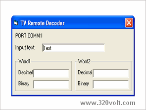
PIC16F628 TV Remote Control Decoder

INFRARED TV REMOTE DECODER
This device decodes the TV remote control into RS232 code. There are many infrared code systems in use, they vary in the number of bits in a word and the number of words. The encoder works fine when used with a TV remote that transmits 16 bits, i.e. the JVC remote, when used with TV remotes that transmit more than 16 bits, a few keys will give the same output from the encoder. The output of the converter is connected to the serial port. Added a Visual Basic code to read the numerical value of the converted infrared.
The common waveform for most IR systems is the beginning of a low pulse of 9.6 mS, followed by a positive pulse of 4.5 mS, and then bits. A bit pulse of 1.2 mS represents a binary 0, and a pulse of 1.8 mS represents a binary 1. This encoder measures the duration of the pulses and creates 2 words of 8 bits and sends them to the serial TX on the PIC16F628.
You can find more information about infrared here and serial interface here.
The software includes PIC code and VB6 code (10KB). You are free to use the circuit diagram and software without limitation.
Pin 4 on the serial port is converted to +12V by the software that enables RTS. Regulated as 5V by 78L05. 5V is the supply to the microcontroller.
Pin 3 is at -12V and pin 7 is constantly at +12V and they are used to drive the RX input between -9V (input HIGH) and +8v (input LOW). These levels are sufficient to drive the RS242 input.
The BC237 and BC327 transistors are the level shift of the PIC output from 0 to 5V, to about +/- 5V required for the serial port.
The PIC16F628 includes a UART for the serial communications port. Pin 8 is UART output, it transmits 16 bits in RS242 format.
It is a receiver for IR detector, infrared remote control systems, PIN diode and preamplifier. It may be TSOP1138, TSOP1238, SFH 506-38 or equivalent.
Source: http://www.moty22.co.uk/ir.php Download TV Remote Control Decoder Alternative link:
Password: 320volt.com
Published: 2010/04/27 Tags: microchip projects, microcontroller projects, pic16f628 projects
MPLAB integrated CCS C Projects Circuits
Earlier Serdar ÇİÇEK “CCS C with PIC Programming” book owned and distributed free of charge CCS C applications I shared many projects had new applications are still plenty of microcontroller varieties more 16F628, 16f84, 12f675, 16f887, 16f876 and so on.
In almost all applications of simulation isis’s dosyalarıda with CCS C LEDs, servos, serial communication, display, eeprom, spi mmc card, usb led, sensor circuits in some instances also in the Software’s computer