Microcontrollers are not good with explanations will not do much about the circuit 🙂 but prepared for the project with eagle pcb, diagrams, and Visual C + + asm prepared progrogra my PC (have source code) is.
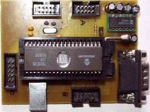
Holgi’s PIC16C765 USB Test Board
Microchip PIC16C765 or PIC16c745 USB controllers are nicely suited to experimentation when no easy silly USB port however want a chip with programmable built-in intelligence. Since that is for USB 1.1 units LowSpeed it shouldn’t must hurry. The USB interface gives the controllers give 1.5Mbit / s, however the information have to be processed within the chip but. It comes ultimately, so on a thousand bytes / s. A knowledge packet with eight byte takes about 8ms. That is sufficient for measurements of slowly altering variables resembling temperature measurements, or to change relays. A CompactFlash reader shouldn’t be constructed higher with these controllers.

The Microchip USB routines require about 2 KB program memory. This leaves 6kB left for their own programs.
PIC16C765 USB Test Board
USB take a look at board format for PIC16C765 (Eagle3.5) and USB demo with supply code (VisualC 5 and MPASM)
This system within the PIC performs the next capabilities: AD values of the 5 analog inputs on PORTA learn. PORTA can’t be modified to digital IO’s with this system!
The serial interface is fastened at 9600 baud, eight, N, 1 set, and may ship and obtain knowledge. However see additionally beneath. The 2 PWM outputs are lively (default DutyCycle zero%). Concerning the PR2 register, the PWM frequency will be modified. All others are set to PORT’s digital IO’s and may be learn and written. The TRIS registers are learn and written to the info course of port’s / Pins change.
The default setting after every RESET: PORTA analog inputs on every little thing besides PORTA4 digital enter. PORTB all outputs PORTC1 PWM Output 1, Output 2 PWM PORTC2, PORTC6 output TxD, RxD enter for PORTC7, the opposite PORTC pins inputs PORTD and PORTE all inputs
If you happen to want different options or another default has to regulate itself to program the PIC’s needs.
The PC demo program reveals the best way to port and reads merely describes how you can change the TRIS registers and learn how to get values from the AD converter. Initially of a pleasant little chase on PORTB and PORTD. But no instance of the serial interface.
It has already been requested a number of instances whether or not the Danch PIC16C765 may be programmed through USB. That is NOT. For this you want a PIC programmer. Microchip hopefully quickly convey out a USB flash controller with a USB bootloader. With the EPROM varieties, the work is simply annoying;)
Sadly, there is no such thing as a Microchip USB driver within the type of a DLL. Though there are VBHIDComm.ocx. A VB ActiveX element. The compiler didn’t embed however my VisualC. The seek for a distinct possibility led to days not till a lot. Till I discovered a web page titled USB by Instance. Hyperlink? Are you watching at www.google.com. The sunshine then introduced into the matter.
The PIC’s are often known as human interface gadgets (HID). No want for the motive force. Win asks additionally if not then to plug within the take a look at board. Within the Gadget Supervisor seems after just a few seconds underneath HID (human interface units), not USB! On an HID compliant machine. You’ll be able to win with these HID gadgets assets board (HID.DLL and setupapi.dll) edit. One should solely know the way. I’ve the entire of some examples of the visible primary web page up collectively, and wrote customized C routines. Don’t ask me precisely what’s being carried out. I have no idea. The principle factor it’s;)
Source: http://home.t-online.de/home/holger.klabunde/homepage.htm PIC16C765 USB Development Board Alternative link:
FILE DOWNLOAD LINK LIST (in TXT format): LINKS-13286.zip
Published: 2010/11/28 Tags: pic development board
Atmel ATtiny15 Microcontroller Example DC to DC Converter Circuit
Atmel ATtiny15 Microcontroller DC to DC converter circuit 3.6 Li-Ion battery voltage of 5 volts raises a more detailed circuit attiny15 not a good example for software power control with microcontroller assembly language prepared by
ATTiny15: 1 – RESET, 2 – UB/2, 3 – UA/3, 4 – GND, 5 – /SHUTDOWN, 6 – output – PWM, 7 – output – /Enable, 8 – UBatt
DC DC converter project