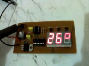
LM35DZ circuit is used as temperature sensors. This sensor is able to output between 0 and 100. The reason for choosing the microcontroller 12F675 and 12F675 jalv2 languages in use in the show as well as the insufficient number of pins used with a controller is to demonstrate how the display.
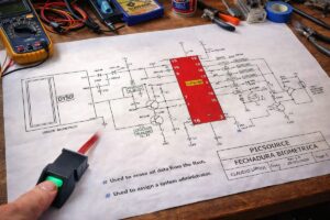
When the circuit actually be done, within the red frame on the right side resistance 3, simulation studies used to ensure a more healthy because it will be used.

Circuit Operation :
About the measuring circuit between 0 and 99 degrees with display screening methods are used. As 12F675 display for processors with low pin count is impossible to use.
Therefore only the port with the second pin multiplexing was performed using the 74HC164. The main point of the selection of 74HC164 integrated processor is using two pins. This allows us to select the display remained, pin 2. 3 seems to display in the circuit diagram. But 12F675-read display uses only 2 to show the degree. The trailing Display shows only the degree symbol.


Thermometer circuit source Jalv2 proteus isis simulation and ares pcb files:
FILE DOWNLOAD LINK LIST (in TXT format): LINKS-18120.zip


10A Motor Control Circuit PIC12F683 PWM
Hello Friends. I have done this summer, an engine control circuit I would like to share with you. While the maxima in the load circuit attracting a stream of about 10 to 12V DC vicinity of a fan I’ve done to the engine speed setting. Circuit works very well. I use my motor 12V at full load, while revenue was approximately 8.5-9 Amps current draw. I used the IRF540 mosfet circuit. This MOSFET 22 Amps if you can take while in full satisfaction. Because of the high current MOSFETs in the circuit are not overheated.