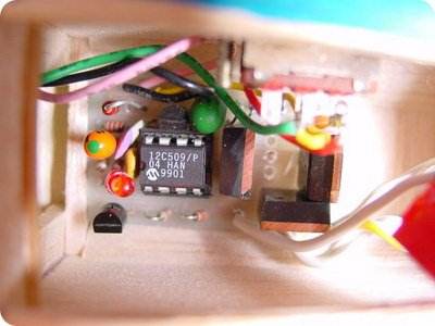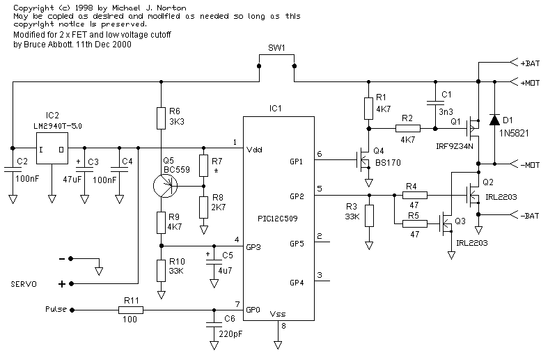
Electronic speed control circuit 12c509 micro integrated outputs are powered by IRL9Z34N and IRL2203 mosfets and motor speed control is provided. All source files of the project (asm codes, eagle pcb, schema) have been shared. Author uses speed control circuit in model airplane projects
Electronic Speed Controller This ESC is based on Mike Norton’s design. I modified the PCB to accept two FETs that increase the current capacity by more than 20 Amps. The circuit is pretty simple as all the hard work is done inside a PIC microcontroller. Brake and BEC (Battery Eliminator Circuit) are optional. The cut-off voltage is adjusted by selecting the value of the resistor R7. The Schottky diode (1N5821 or equivalent) is mounted directly on the PCB instead of the motor.
Double-size prints of your PCB layout at 600dpi or 300dpi at true size. Click on the small preview on the left to get the image, then right click on the full size image and choose “save image as..” If you can’t print at the right size, download this zip file containing the 300dpi and 600dpi BitMap versions.

R7 Value for Different Breaking Voltages Cells Nom. Volt Cut-off Voltage R7
5 6V 4.5V 760 Ohms
6 7.2V 5.4V 390 Ohms
7 8.4V 6.3V wiring
Modifications for 4.8V operation (4 cells and no BEC)
Replace IC2 (LM2940 regulator) with a 15 Ohm resistor from I to O.
R7 = 330 Ohms.
R8 = 2.7V 500mW Zener Diode (or 2 x 1N4148 diodes and one red LED in series).
Power the receiver (and servos) directly from the ON/OFF Switch.
Updated: August 23, 2001
I changed the firmware to improve the fault management. I also replaced the Brake indicator LED with an audible arming indicator. The new source codes are spd400.asm and spd400.inc. The new hex file is SPD400.HEX.
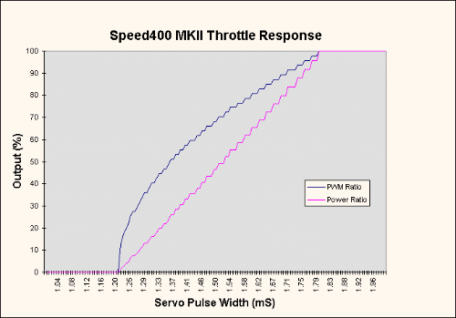
Throttle control is more natural using this inverse exponential compensation. You can see that the middle bar (1.5mS) produces 50% power, whereas an unbalanced throttle only produces 25% power at this setting. The 0% and 100% power flat areas are wide enough to allow full throttle range to be available for transmitters that cannot reproduce the full 1mS to 2mS servo pulse range. Note the ‘step’ effect on chart lines. This is because of the limited number of PWM rates that can be generated (there are 40 steps).

Source: homepages.paradise.net.nz PIC12C509 PWM Electronic Speed Control link:
Password: 320volt.com
Published: 2008/03/09 Tags: microchip projects, microcontroller projects, pic assembly example, pwm circuits, simple circuit projects


Bridge Bidirectional DC Motor Speed Control PWM PIC12F629
Bridges connected motor speed control circuit 12f629 controller based on the PWM method and the motor is driven integrated outputs 2N7002 MOSFETs reinforced with assembly language prepared by the source. Asm,. Hex code and eagle prepared with diagrams, printed circuit board files there.
Fully solid-state, bi-directional output (without relays)
Lightweight materials SMD (surface mount)
10 A Maximum motor current (with MOSFETs)
Auto LVC (Low Voltage Cutoff) for 6 ~ 12V input voltage
For the smooth and efficient control of high-frequency PWM (3kHz)
1 A low dropout BEC (Battery Eliminator Circuit)