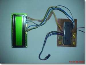
PIC16F877 microcontroller and DS18B20 temperature sensor and digital thermometer with LCD display have all the details. Thanks to those who contributed
In this study, it is aimed to design a thermometer using electronic circuits and microcontroller. In the study, the working principle of the leds that light up in a changing order depending on the perceived temperature and the LCD devices that show the sensed temperature digitally are based on. In this method, body temperature is examined.
The body temperature of a normal person is 37C, and at the beginning of many diseases, the temperature usually rises and in some diseases, the body temperature decreases. For this reason, devices that measure body temperature and called thermometers have been designed to understand diseases.
First of all, a brief information about the thermometer will be given, and then information will be given about the materials used. In the next section, information about the applied method will be given, and the designed system will be explained with block diagrams. Then, explanations about circuit diagrams and circuit designs are made. Finally, information about the result and the point reached so far will be given.
In general, there are three types of thermometers: Celsius, Fahrenheit, Rheum. They are the same as each other in general structure. What is different is the numbers on them. This is due to the fact that the boiling point is taken differently in each of the three.
Although the freezing point of water is 0 in all three thermometers, the boiling point is accepted as 100 in Celsius, 212 in Fahrenhelta, and 80 in rheomur. Other than Oiva thermometers, mineral and alcohol thermometers were also made.
Digital Thermometer
Digital thermometers usually measure body temperature. However, since it is digital, they can read for a long time; however, it is the type that can measure the fastest among thermometers.
The mercury thermometer also measures body temperature, but it takes longer to measure than a digital thermometer does. It is also known as the “body thermometer”. It is used in medicine.
Patient Thermometer
It is a mercury thermometer. It is used to measure body temperature. It measures temperatures from 35 degrees Celsius to 42 degrees Celsius with 1/10 accuracy. There is a knuckle at the junction of the chamber and the capillary tube of these thermometers. After measuring the body temperature, the thermometer is held by the handle and shaken. From where? The body temperature is measured by placing the thermometer, which is ready for a new measurement, in the mouth or under the armpit.
*In this project, it is aimed to make a digital thermometer based on PIC microcontroller.*
MATERIAL LIST USED
1) 1 pcs 16F877 model pic
2) 1 x BS18B20 temperature IC
3) 1pc 20MHZ Crystal
4) 2 x 22Pf Capacitors
5) 9pcs 10K Resistors
6) 1 pc LM016L LCD
7) 8 yellow and 1 green LEDs
8) 1pc 5V adapter
9) 1 pull-up resistor
For the design of a PIC microcontroller-based device that measures and properly displays body temperature, a temperature sensor that detects temperature, a PIC microcontroller, LED or LCD that displays the measured temperature are required.
Temperature sensors are generally analog or digital. The outputs of analog sensors are analog voltage or analog current, and this voltage or current is usually directly proportional to temperature. It is necessary to use an analog-to-digital converter circuit to connect analog sensors to the microcontroller. Many PIC microcontrollers have analog-to-digital converters. There are 8 analog-digital converters, each of which is 10 bits, in the PIC16F877 microcontroller used in the project. In reality, there is only one analog-to-digital converter and 8 analog inputs can be connected to the microcontroller thanks to a multiplexor.
We used LED and LCD to show the detected temperature in the project. We measure the temperature by looking at the temperature displayed on the LCD screen and looking at the burned LEDs. Although the measurement with LEDs is not accurate, it can be used to measure body temperature. The temperature sensor we use is a three-legged sensor. One leg is +5V voltage, the other leg is ground, and the third leg is output and is connected to the analog input of the microcontroller.
DS18B20 Digital Temperature Sensor


Thermometer circuit diagram

PIC16F877 LCD Digital Thermometer Circuit DS18B20 schematic proteus simulation source code files:
Password: 320volt.com
Published: 2009/05/12 Tags: microchip projects, microcontroller projects, pic16f877 projects
PIC12F675 Electronic Doorbell Melody Circuit Proton ide
@ Mustafa my brother’s work is based on PIC 12F675 4 can play the melody software prepared by proton ide
I used pic12f675 circuit. In fact PIC16F84 was going to use but 84 to 4 units melody is taking pic 675’t to. Circuit energy we give the LEDs dim press the button when LED is lit and the first melody starts playing the first tune when we’re led off and the button is pressed again the beklenir.buto again we press the LED again lights up and the time 2 plays the melody plays four tunes continues until the button is pressed again after 4 melody will return to the first melody
Electronic Doorbell Circuit Schematic