Nixie lamp Thermometer DS18B20 Circuit with ATtiny2313 The first Nixie lamps appeared in the mid-twentieth century. For many years they have been used in a variety of apparatuses but have been supplanted by newer VFD displays and LEDs. For decades, forgotten again, they returned to grace in retro electronics projects of hobbyists as well as a wider audience thanks to increasingly popular commercial projects. The digital sensor measures the temperature with a resolution of 12 bits and a frequency of 0.5 Hz (every 2 seconds). In order to eliminate possible sensor errors, a range of accepted temperatures has been introduced from + 10 ° C to + 44 ° C. All values outside the range are considered erroneous and are not considered.
Nixie Thermometer Circuit diagram

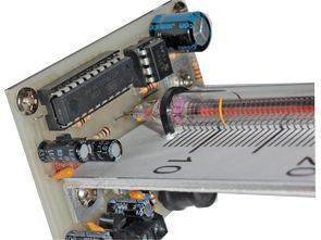
The Nixie thermometer schematic diagram is shown in Figure 1. The heart of the circuit is the ATtiny2313 microcontroller running on an internal RC oscillator with a frequency of 1 MHz. As a temperature sensor, the popular DS18B20 chip is used to measure from -55 to 125 ° C with a maximum resolution of 12 bits. The U1, together with the set of external components, stabilizes the 5 V voltage used to power the digital part of the thermometer
Due to the high flash voltage of the lamp, the MC34063 voltage suppressor inverter was used. The MOSFET T1 transistor, along with the gate-stop resistor R3, acts as a key. During conduction of the transistor the L1 choke stores the energy in the form of a magnetic field, and the diode D1 is polarized by blocking the C7 capacitor before discharging.

![]()
FILE DOWNLOAD LINK LIST (in TXT format): LINKS-25856.zip
Published: 2017/10/01 Tags: avr project, microcontroller projects
Nixie Röhren-Thermometer-Schaltung
Nixie Lampe Thermometer DS18B20 Schaltung mit ATtiny2313 Die ersten Nixie Lampen erschienen in der Mitte des zwanzigsten Jahrhunderts. Seit vielen Jahren werden sie in einer Vielzahl von Geräten verwendet, wurden jedoch durch neuere VFD-Anzeigen und LEDs ersetzt. Jahrzehntelang wieder in Vergessenheit geraten, gelangten sie dank der immer populärer werdenden kommerziellen Projekte in Retro-Elektronik-Projekten von Bastlern und einem breiteren Publikum wieder zu neuem Leben. Der digitale Sensor misst die Temperatur mit einer Auflösung von 12 Bit und einer Frequenz von 0,5 Hz (alle 2 Sekunden). Um mögliche Sensorfehler zu eliminieren, wurde ein Bereich angenommener Temperaturen von + 10 ° C bis + 44 ° C eingeführt. Alle Werte außerhalb des Bereichs werden als fehlerhaft angesehen und nicht berücksichtigt.
Nixie Thermometer Schaltplan