A simple led animation (flip flop) circuit with NE555 Timer IC. You can adjust the flashing speed and brightness of the LEDs with the tirimpots on the circuit. There is a pcb drawing of the circuit. You can arrange the leds according to the shape you want. The supply voltage of the circuit should be 9 volts dc. 100 LEDs can be used.
555 Flip Flop Smile

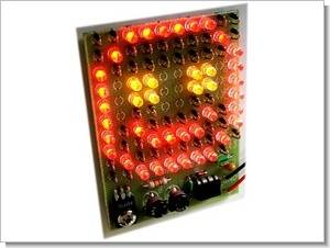
Flashing 10×10 LED model
The maximum consumption of 0.5 A may seem huge to power from a nine-volt battery, but by setting the minimum light duration and the lowest blink frequency, the demands on the consumption of the entire device are significantly reduced.
The circuit uses the 555 circuit, a standard integrated pulse generator, and there are a number of simulation programs for it. We also used today’s simulation software while designing the circuit diagram. The frequency here is primarily determined by Capacitor C1 and trimmer TR1. If you want a longer, lower frequency, simply choose a larger capacity C1.
Assuming you’re using the components that came with the kit, you’ll go from 1 Hz to an oscillating rate that gives the impression of a constant brightness (However, the power consumption is much lower than ours, as the on/off states still work. They fed the image in keyless mode – directly from the battery, for example.) Trimr T2 it mainly determines the change, that is, the time ratio of open/closed states.
Since we can load the 555 circuit with a maximum of 200mA and our figure may have a consumption of over 500mA, we need to switch the leds using the NPN TESLA KD135 power transistor (or foreign equivalents). For a simpler PCB design and the possibility of powering the connection directly from the 9V battery, we chose to connect the display as a set of 33 units of three LEDs connected in series.
Each unit needs to be closed circuit to be lit – we will either equip them all with LEDs or replace the diode with a resistor if necessary – you will use this option especially when creating figures. As soon as one of the three diodes in series is lit, none of them is lit. The same applies to the combination of LED and resistor (remember the lighting of the Christmas tree with old electric candles, when you turn off the entire circuit by removing a light bulb)
In the picture of the layout of the components, we can see the grid dividing the screen in a trio of LEDs connected in series. After installing an LED diode in the trio, we need to fill the remaining space of the trio with other diodes or resistors. Of course, if you don’t attach any LED diodes to the trio, you don’t need to fill it with three resistors – then we don’t need to turn off the electrical circuit and leave the trio unplugged (you can see it in the making of the smiley face).
The wiring for the last row is completely different – shown in red and yellow. Red: Diodes are always connected in three parallel and at the same time these three triples are connected in series. As soon as we install an LED in the zone marked red, it is necessary to install all of them with additional LEDs or resistors. Yellow: As we assemble an array of 100 LEDs from 33 triples, we have one diode left. It is connected with only one primary resistor R5. Therefore, you can fill in the yellow field or leave it blank.
Layout of PCB components
Soldering individual LEDs can be very tedious. We helped ourselves with a third hand and a sponge. We pushed the smiley face-forming saltpeter all the way in and covered the printed circuit board with foam. This allowed all diodes to be pressed to the port without being scratched. Then it is enough to solder one diode after another. Resistors that replace LEDs are of a miniature design, rated at about 300W.
They slide vertically. The printed circuit board is designed in such a way that SMD1206 type resistors can be soldered next to the connections. If the flasher is set reasonably, the switching transistor does not need to be cooled by a heatsink. Just use a screw to bring the heat to the circuit board. Solder the mother to the tin plate near the connections.
Do not be surprised if the entire connection gets hot during operation (due to heat conduction to the connection), the device can even work at 80°C. After correct assembly, the connection is immediately ready for operation.


source: stavebnice.richardvacula.com
Published: 2009/09/20 Tags: 555 timer circuits, analog circuits projects, led projects, simple circuit projects
TV Oscilloscope Circuit with ATmega8515 ATtiny12
Attiny12 ATMEGA8515 a very interesting project based on digital solid-source software and schema files, PCB’s drawings for people working with Atmel series microcontrollers can give different ideas can be useful in different projects analogue solid
The tv oscilloscope is undoubtedly one of the basic instrumentation in electrical engineering. Oscilloscopes are available in two basic designs – analog and digital. Amateur analog oscilloscope design is relatively complex and expensive, while the construction of the digital oscilloscope is due to the availability of microcontrollers much easier. One of the basic elements of each oscilloscope’s display unit. For analog oscilloscopes can be found with osciloskopickými screens. Modern digital oscilloscopes use different displays, which are often very expensive. Therefore, some structures conceived as modules that can be connected to a computer. Data is then displayed using the software installed on the computer monitor.
TV Oscilloscope Project