PIC16F877 Experiment board ACCEL P-CAD PCB PCB and schema files V14.00.3 asm code through the sample has been prepared by the addition
You will find on this page all the elements to achieve a map of development for PIC16F877. s une application.it can be placed directly in an application. Reboul pour implanter le “bootloader” dans le PIC. We used the PIC sold 49.33 € 01 HT by institutions Reboul to implement the “bootloader” in the PIC. The program is most useful in the future, because the programming is done in situ using the serial port of a PC.
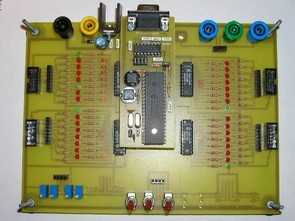
PIC16F877 development board

Card Features PIC_DEVEL: Power supply 7v to 12v protected against reverse polarity
LED display by 32 statements of PORTS A, B, C, D ETE
8 inverters to generate logic levels on inputs PIC
8 knobs to generate tension on adjustable analog inputs PIC
4 connectors to link HE10 entry / exit PIC to other cards
4 sockets to connect 4mm output of the ICP to a measuring device
The connections between potentiometers (or inverters or 4mm socket) and inputs / outputs of the PIC is with simple bare son inserted in a row connector contact.
MAX232 R4 and R5 are not on the pattern established: they were intercallées between MAX 232 (pin 9 et12) and PIC16f877 (RB2 and RB7). (He had cut the tracks that linked directly to the PIC Max) This allows for the pin RB2 and RC7 ICP output without creating conflict with the output of MAX232

The jumpers J5 to J8 are unnecessary (to be replaced by son), Pins RB3, RC6, RB2 and RC7 CIP can easily be used as inputs or outputs in an application, the risk of conflict with the MAX are avoided thanks to R3 and R4.
The jumper J7 was replaced by a push button J7 not included in the scheme of establishment (see photo): J3 pressing Reset single product, while pressing J3 when J7 is already supported causes loading a program by the serial link. (this provided they use the bootloader “bootrt.asm” testing the RB1 Reset).
Source: stielec.free.fr/ Microchip PIC16F877 Testing, Experiment Board schematic pcb files alternative link:
Password: 320volt.com
Published: 2008/11/21 Tags: pic development board, pic16f877 projects
Atmel Atmega32 Testing, Experiment Board
PCB and schematic P-CAD 2004 Schematic drawings prepared by V18.00.2690 also available in C language prepared by the test code through
You will find on this page all the elements to achieve a map of development for ATMEGA32 Power 7v to 12v (4mm sockets) protected against reverse polarity Visualization by 8 LEDs statements of eight logic outputs (your choice according HE10 connector wiring entry porta, PortBait, PORTC, PORTD output keyboard or encoded)