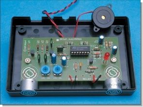
With two MA40A3R ultrasonic sensors, you can adjust the distance settings of the car parking sensor circuit with the vr1, vr2 trimpots. The circuit can work directly from the 12 volt car battery and gives an audible warning with a buzzer.
Ultrasonic Analog Parking Sensor Project

UPDATE
One of our readers, @Yusuf Usta, applied the circuit and shared the details, thank you.
Preface;
Technology has advanced. Heat, light, wetness and humidity, distance, sound etc. I have designed a circuit that perceives distance from these wide possibilities that perceive many things such as and put them at the service of people. I would like to thank everyone who gave me the opportunity to carry out this study, which gives an audible warning to prevent the vehicle approaching a wall or similar obstacle from colliding with the help of ultrasonic sensors, and who contributed to my acquisition of this information.
In this study, it has been tried to determine the distance from this amount of echo by taking the echo of the ULTRASONIC AUDIO SIGNALS LEFT INTO AIR. circuit; working principles are explained, construction stages are shown, and cost analysis is made.
Sensor Features,
ULTRASONIC SENSORS
Ultrasonic sensors are generally used in robots to avoid obstacles, navigate and map the location.
Working Principle: The ultrasonic distance sensor works by emitting short pulses of 40khz ultrasonic sound from the piezoelectric transducer. A small part of the sound energy is reflected from the objects in front of the sensor and comes to the detector, that is, to a different piezoelectric transducer. The receiver amplifier sends the reflected signal (echoes) to the signal detection system or the microcontroller. Depending on the speed of the signal in the air, the microcontroller determines how far the objects are by running a timing process.
Ultrasonic distance sensors are physically available in two types. However, their basic functions are the same.
· Polaroid sensor type: The propagation and detection of ultrasonic sound waves is done by a single piezoelectric transducer.
· Hitechnic sensor type: The propagation of ultrasonic sound waves is made by the transmitting transducer, and the detection of the waves is by the receiver transducer. In this type of distance detection, 2 transducers are used.
When processing according to the rotation time information of the reflected sign in ultrasonic sensors, some interpretation errors can be made due to ambiguity. For example, let the face of the sensor be parallel with a flat object closer to itself. However, sometimes the rotation time information of the reflected signal may mislead us in perceiving the meaningful object. If the surface where the object is located is angularly scaled with the real surface of the sensor, the information information is recorded according to the closest point within the 30 degree cone.
Technical and Physical Information:
Resonance Frequency (40 KHz)
Sound Pressure Level (less than 115 dB)
Sensitivity (less than -64 dB)
Radius (16.2mm)
Height (12.2mm)
Terminal Spacing (10.0 mm)
Usage Advantages of Ultrasonic Distance Sensor: Contactless Measurement It measures from relatively large distances using the air without touching the target object.
Object Range: It can measure object distance mostly by appearance or proximity analysis. Output Proportional to Distance: The electrical outputs of the sensor are proportional to or dependent on the measured target distance.
High Resolution: Ultrasonic sensors are capable of displaying accurate and subtle differences in information about the target object. Unaffected by Optical Characteristics of the Target: Ultrasonic sensors’ detection is not affected by the light level of the environment, the color of the target, or the optical transmittance/reflectivity properties of the target.
Sensitivity: Can detect large or small objects
Some Typical Application Areas:
a) Approach Application: They are used in industry to detect the presence of objects in a certain place, by counting them or to control their movements.
b) Dimensioning: They are used to determine the size information of objects according to the widths or volumes of the objects.
c) Level measurement: It is used in industry to measure the level of liquids or materials in liquid form in tanks or boxes for inverters and arrays.
d) Coil Diameter Measurement: They are used in industry to measure the control tension or speed of the rolls, or the full/empty state.
e) Classification / Selection: The process of classification or selection of objects is measured depending on the differences in the physical dimensions of the objects.
f) Disconnection Detection / Loop Control: It is used in printing, to detect and detect broken network connections of paper machines so that the process can continue quickly.
In addition to these applications, ultrasonic sensors;
vehicle alarm systems
lighting control
Parking support systems
It is also frequently used in industrial applications such as automatic door control.
Working Principle of the Circuit
The circuit is based on the principle of radiating the 40 Khz sound produced by the 4093 integration with an ultrasonic sound emitting sensor, and detecting and evaluating the rotating part of this emitted sound from the objects it hits with its ultrasonic sound sensitive receiver.
PCB Labcenter Electronics Proteus ares software was used for re drawing.
c8050 transistor features: It is a power transistor that can output 2W. B type class push-pull amplifiers have been used for many years, especially in portable radios. It has a withstand voltage of up to 40 volts.
Circuit diagram:

Assembly details
When installing the materials, it is necessary not to install the transmitting and receiving ultrasonic transducers in reverse. Diodes should not be reversed. I added a zener diode 6.2 volts and a 470 ohm resistor, which is not in the diagram. Because in this device, which we will run with a 9volt battery and even use a 12v battery in vehicles, the voltage had to go down to 6.2 volts somehow. More voltage will damage our circuit.
WORKING PRINCIPLES OF THE CIRCUIT
40 Khz audio signal is given to the tx sensor in the circuit with the R/C resonance created in the q2 transistor. This is the RX sensor that detects the part of the audio signal that hits an object and returns. These received audio signals are pre-amplified with the q1 transistor. This signal is applied to the legs 12 and 13 of the 4093 IC. 4093 is a nand gate IC and has 4 double input inverters. The sensitivity of changing the logic state of the door is adjusted with the vr2 trimpot.
There is a loop here. As Q2 is triggered and grounded, the transmitter sensor remains in a load state between negative and positive energy. Thus, there is interaction with each other in both the transmitter and receiver sensor operation.

sorce http://www.siliconchip.com.au/cms/A_102713/article.html
Ultrasonic Parking Sensor Circuit schematic pcb files alternative link
Password: 320volt.com
Published: 2009/02/04 Tags: analog circuits projects
Atmel AVR Circuits Projects Archive
For years I have collected from many sites in the internet environment projects in various Atmel AVR works with the idea of a day of work habits archive a grown male. Atmel is sure to be a solid resource for people interested. projects thanks to those who contributed to preparing
Atmel Projects