Circuit made a long time ago and has been tested. There were a problem in the operation and construction. We must do BDX53 your engine is larger output transistors. 5 and 6 pin motors can be run with the circuit.
Four-ended output transistor to run the engine to be increased. So four BC327 should be added. If you want to add BDX53 transistors transistors used should be BDX54. Our next meeting will present such a circuit.
3006 multi-turn potentiometer P1 type setting using the maximum speed should be done with it. Pots brought to the maximum value of the motor is caused to rotate slowly. P2 according to the minimum value after the engine speed is caused to rotate.
P2-turn potentiometer is set at the maximum speed of the engine. Thus, the setting can be made. Now the circuit is ready for use. Motor terminals should be connected as shown in the connection.
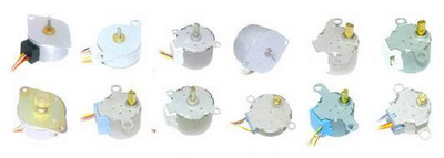
555 Stepper Motor Driver Schematic

Published: 2008/08/25 Tags: 555 timer circuits, power electronic projects, simple circuit projects
Remote Controlled Toy Car Project PIC16F877 PIC16F628
software CCS used N channel FETs with a 60 amp motor drive circuit and used for different applications control circuit PIC16F877 24c08 eeprom and ICL7660 used CCS EEPROM communication with examples of how you can also control circuit MC33063AP made with dcdc converter circuit and 5 .12 v input 12 … 19v output 12 … 18v input 28v output short, you can get enlightened or different project ideas that could
Remote Controlled Toy Car