The base consists of circuit LM2576-ADJ, belonging to the group of highly integrated circuits, so that the proper function of just a few external components. Basically, it is a step-down converter with adjustable output voltage for constant current up to 3A. When buying circuit is necessary to buy a circuit with the surname Adj. Similarly labeled perimeter without Adj from production fixed at 5V output voltage without the possibility of regulation. The output voltage can be as same as input or less. The opposite function with only a slight modification of the wiring should be used as circuit LM2577-adj
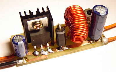
LM2576 DC DC Converter Circuit

For proper operation of the inverter is necessary coil with inductance about 150uH. Its current capacity depends on what you require from the drive. It’s good to be wound on a toroidal core with a diameter of 25 mm. They can be used as coil vypájené eg PC resources and other pulse techniques. Fully complies with yellow marked core. Specifically, it should be wrapped around the yellow toroid diameter 27 mm 45 turns of wire of 1mm. This coil can buy in stores GES electronic. The output can be further equipped with a coil for improved smoothing of the output voltage. The filter capacitors must be built to the required voltage.

• 3.3V, 5V, 12V, 15V, and adjustable output versions
• Adjustable version output voltage range, 1.23V to 37V (57V for HV version) ±4% max over line and load conditions
• Guaranteed 3A output current
• Wide input voltage range, 40V up to 60V for HV version
• Requires only 4 external components
• 52 kHz fixed frequency internal oscillator
• TTL shutdown capability, low power standby mode
• High efficiency
• Uses readily available standard inductors
• Thermal shutdown and current limit protection
• P+ Product Enhancement tested
Source: pokusy.chytrak.cz/
Published: 2008/08/03 Tags: dc dc converter circuit, power electronic projects
433MHz RF Transceiver Circuit with PIC16F84A (6 Channel)
RF Transceiver circuit PIC16F84A microcontroller is used in the 2 transmitter and receiver circuit diagram rf modules to be connected to the pins marked on the resource. Has bass and isis simulation files. RF Transceiver Modules atx34 the most common ones in the market, arx34
PIC16F84 433MHz RF Transceiver