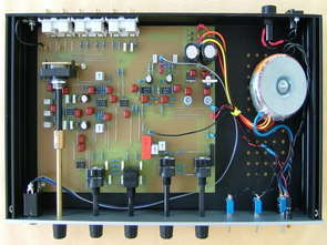
Preamplifier 10 to six channels for SACD and Home Cinema The preamplifier to six lanes that we present is intended to pilot a HI-FI to five or six channels. You will appreciate the quintessence of new SACD or simply to give tone to your Home Cinema”.”He will find its place in your system if your player does not have volume control. This project is the first part of a project comprising a series Monoblock Power 5-way tube that will be presented in our editions.


This achievement is a direct reference to the RIAA preamp appeared in the LED 187 and 188 of January and March 2005. We wanted this achievement for a similar approach while providing substantial savings due to the use of dedicated integrated circuits. The specifications obtained have little to be ashamed of its big brother: the deviation from the standard RIAA does not exceed 0.25 dB and total harmonic distortion is less than 0.1%. The circuit board is scheduled for two configurations: entry for mobile cell magnet and coil cell phone.

The preamplifier allows the selection of 5 sources, including a correction RIAA. It has an exit 1 Veff under 600 ohm and includes an amplifier for high fidelity listening with headphones. His own distortion is less than 0.03% and bandwidth ranges from 10 Hz to 50 kHz at -1 dB. The collection takes on a single card and use only integrated circuits which makes his achievement to everyone. The card can be shipped in a box extra dish of 40 mm high.
Source: novotone.be/ 3 Preamplifier project pcb schematic alternative link:
Password: 320volt.com
Published: 2008/10/27 Tags: audio control circuits
High Voltage Laboratory Power Supply Circuit 50V to 450V 500mA
Laboratory Power Supply Voltage adjustable from 50 to 450 volts in a current of 500 milliamps, with a stable 0.1% 100Hz ripple and noise factor: <1 mV pp on the range. The internal resistance is <0.5 ohm static and <1 ohm dynamics of 10Hz to 100KHz. The control circuit is simply a high voltage amplifier. Here we find two SIPMOS BUZ80 (Q2, Q3) connected in series ballast to distribute dissipation. These transistors are controlled by a third SIPMOS BUZ80 (Q1) mounted in a common gate. The ratio of the source resistor (R4) and 470Ω load resistors collector Q1 (R5, R6) of 200K, gives us a gain of 400. However, a portion of the output voltage equivalent to 1/20 (R14/R12 + R13 + P2) is fed against negative feedback circuit in the gate of Q1 and we reduced the total gain at 20. We will see later against the benefits of this reaction.