The operation of a transistor amplifier for beginners. Integrated transistor amplifier from a mediocre competitors an example of how cheap it is superior, actually.
I found a diagram in a foreign forum, I wanted to introduce a quite simple and low cost circuit.
low-cost amplifier schematic


Quite an old history in 1974 schema and extends to three years. True if the schema FAIRCHILD The design of the company says. In this circuit, naturally hi-end or Audiophile don’t expect results, but this sound is bad, Don’t get it either.

TDA2030, TDA2050 and similar integrated amps, I can say that has better sound, especially at low volumes, even while their heads is pretty solid. Of course, everybody has their own assessment will be different.
The schema I found in the forum who doesn’t like the sound of this circuit have liked. Same Forum, “published inHP333 distortion analyser” with the device measured distortion values is shown below. The accuracy of the results, of course I don’t guarantee.
Distortion vs frequency
1khz 0.07 %
10khz 0.08 %
20khz 0.1 %
30khz 0.12 %
Distortion vs power output at 1 khz
0.5 watt 0.17 %
1.5 watt 0.12 %
4 watt 0.05 %
12 watt 0.16 %
17 watt 0.5 %
20 watt 4 %
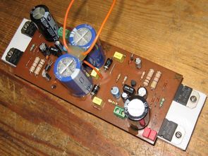
This amplifier more entry-level users, although experienced users might seem that will attract the interest of bored, I think. A pair of transistors tip142 and 147 in this circuit the output again even as I used to, but the real ones not fake ones. TIP122 TIP127 that may be suitable and also are actually easy, and they’re not expensive.
You don’t have to use FR302 feed on the floor. I used to have them in my hands at that moment.
At a value of at least 3 amperes at 50 volts is suitable, you can choose a rectifier diode. For example, 1N5408, etc.
A simple aluminum cooler way to cool transistors in the output stage of the circuit we need the most. Your attention at this point between the output transistor 32mm. I would like to draw to the heart of. Accordingly, we have designed transistors and PCB as a coolant because Yi in this way we settled, we have a different solution for this circuit. Aluminum heat sink in the event done on the Cheap to get at a time as we use the binary curtain the curtain rod that we use in our homes.
After cutting, any burrs on the edges with a file it takes, and we’re polishing it up and clean the whole surface with sandpaper.
They’re making it out of plastic, but I’m sure you can easily find in the junkyard.
In the circuit you can see in the picture is approximately 20cm. length of the cooler is more than enough. If you want to run at full power there for hours, longer than the curtain rod, cut it off.

If you push and flex the circuit from above, we need to isolate this part as the connections under the circuit will be shorted on the refrigerant. We cover this place with a suitable insulating material. A thin linoleum or something like a plastic tarpaulin can do the trick. It’s better if you can find a thermal pad. 15cm to the channel in the middle of the cornice to support the bottom of the circuit. We put a piece of rubber to prevent the flexing of the circuit.
Try to give 30 volts AC circuit wires into the orange finished now.


2N5961 can be used instead of following Transistor cannot be found in the picture placement was shown the difference BC550

Amp Part list:
R1 10 K
R2 15 K
R3 120 K
R4 150 K Trimpot
R5 150 Ohm
R6 47 Ohm
R7 4,7 K 0,5W
R8 1 K 0,5W
R9 2,2 Ohm
C1 10uF 25V
C2 22uF 50V
C3 100uF 50V
C4 220uF 10V
C5 2200uF 63V
C6 100pF 63V
C7 470nF 63V
C8 4700uF 63V
C9 4700uF 63V
C10 470nF 63V
C11 470nF 63V
C12 2X680nF 63V
D1 1N4148
D2 1N4148
D3 1N4148
D4 FR302 (1N5408)
D5 FR302 (1N5408)
D6 FR302 (1N5408)
D7 FR302 (1N5408)
Q1 BC550C (2N5961*)
Q2 TIP142
Q3 TIP147
Amplifier circuit pcb files:
FILE DOWNLOAD LINK LIST (in TXT format): LINKS-25420.zip
Published: 2016/04/22 Tags: audio amplifier circuits, transistor amplifier
Germanium Transistor Amplifier Circuit
Once AD161-AD162 I had an experiment with pair. I still use almost every day. At first I didn’t like the sound, but I like listening to. The frequency of particular speech sounds very clear and is understandable.
Quite a while (probably has been for eighteen years) and two ad162 ad161 a pair of them in my hand I was looking for a cooler appropriate.
Thanks to our friend s in the hands of AD162 sent and thus we set to work. Our expectations were not very high even though we have to use what we have and we became the owner of both a classic amplifier.
Amplifier Circuit
Hochwertige Kostengünstig Verstärker 20W
Der Betrieb ein transistor-Verstärker für Anfänger. Integrierter transistor-Verstärker aus einem mittelmäßigen Konkurrenten ein Beispiel, wie Billig es ist besser, eigentlich.
Ich fand ein Diagramm in einem fremden forum, ich vorstellen wollte eine ganz einfache und kostengünstige Schaltung.
Kostengünstig-Verstärker Schaltplan