There is a pcb file prepared with the schema sprint layout prepared with Splan. You can download the driver file for your operating system from the ftdichip site. USB to UART converter module FT232RL Due to the fact that many modern computers do not have a COM port output (almost all modern laptops), the problem of connecting a device in an MK to a PC is very common. FT232x series chips will help solve this problem.
In the FT232x family, the FT232R is of particular interest. This microcircuit is an almost ready-made solution that connects to a PC via USB and has UART signals at its output. These signals are understandable for any MK (including those implemented in software). Two of these are sufficient for a simple connection – TX and RX .
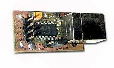
The switching circuit of the FT 232 RL is very simple and contains very few elements. The only difficulty in repeating this is the size of the microcircuit itself – it has a very small leg pitch (0.65 mm) and their thickness (0.3 mm). To desolder the module circuit, you will need a soldering station and experience in soldering SMD components (according to the manufacturer, the FT 232 RL chip is able to withstand overheating and is well protected from static, which allows desoldering with an ordinary soldering iron finely sharpened tip). The rest of the items do not cause any special problems when soldering. There is also a jumper on the board where you can power your device from the USB port (max 500mA !!!).
FT232RL PCB USB UART

Source robozone.su/mrc28/23-modul-konvertera-usb-uart-ft232rl.html USB UART Circuit FT232RL schematic PCB
Password: 320volt.com
Published: 2008/08/23 Tags: analog circuits projects
Stick Mixer Circuit
The Stick Mixer, to stick to Melody and Bass entered the first stage operational amplifiers, amplify each twice, the second operational amplifiers in the mix. Third step is the second mixer circuit inverted signal back to a positive phase. Mixing process, given the non-inverting amplification Low Cost first stage is to TL072, 2 second to third step is to use the NJM5532. This op amp is TL072, NJM4558, NJM4580, NJM5532, NE5532 in comparison to the audition decided.
Op amp mixer circuit