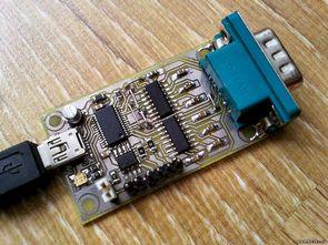
Introduced 3in1 converter device: USB – RS232, RS485, and UART. Fully dedicated to the role of the FT232RL converter is visible in the system as a COM port, and is supported by two MAX232 and MAX485 systems. All settings for the converter are made by the system, as in the normal speed of the COM port supports 110 – 921600 bps.
A double-sided plate with a size of 30 mm x 58 mm, all for surface mounting of components, except the terminal COM (DB-9M, male DB9). On board there are two LEDs, a red and a green TX RX pins connected to the CBUS1 system, CBUS0 and FT232R. Current limiting resistors are usually 270ohm, but choosing them for high-power LEDs, red usually requires a lower voltage.
There are three connectors:
232 – the role of the voltage translator TTL – V.24 MAX232 have two bones. You can use the special converter MAX211, but it is much more expensive and harder to get it, so I decided, however, a cheap and ubiquitous MAX232. The only drawback is the lack of a ring conversion line, but almost never used in other devices. Pump system load voltage generation +9 V and -9V, necessary to ensure compliance with V.24. 232 Reverse logic layouts high state on input and low output and vice versa.
485 – In addition, the board has RS485 converter circuits (here SN75176), its transmitter is controlled by the line from the T2DEN pin CBUS2 of the FT232R system, so it is active only when sending a character, and this will be done automatically. Its receiver in the converter is configured by assigning specific functions to a pin CBUS3 FT232 layout. We do this with services that I will describe below MPROG. “TXDEN” – the receiver will be on all the time, but will be disabled automatically during transmission – do not receive echoes. “PWRON” – the receiver connected permanently, you will receive an echo. “I / O” – receiver, output in high state, impedance, does not block reading lines allows you to use another converter connector. Note – By default, the receiver works! Differential output and B in the form of goldpin? W, the board also attaching a jumper resistor 120ohm Terminator.
UART TTL – So TxD and RxD TTL lines are standard goldpin? W, obtained in the form of direct connection to the system using asynchronous transmission voltage 0V-5V level, such as microcontrollers. RxD pin is used in conjunction with the output of 232, which is impossible to turn it into a high state when the resistance of the system is not used (0V RS input). In exchange for such entry conditions, a high state is given at the RxD pin preventing it from immediately exchanging with another suitable device. The simplest way to solve this problem was to combine the output of the system to read the line through the 10K resistor – the FT232 system receives data correctly and uses a different transmitter On the current UART TTL interface you need to download an RxD pin no more than 1 mA.
FT232RL integrated USB port using the RS232 serial conversion can be done also RS485 and UART converter is done in this circuit all in one single printed circuit on the PCB layout is also very stylish been unilaterally particular microcontroller projects also will be useful tool .. Also FT232RL manufacturer’s instructions (Future Technology Devices International) prepared “mprog” (mprog EEPROM Programming Utility) with various EEPROM program is said that this circuit http://www.ftdichip.com/support/utilities.htm#mprog

Notes:
To test system 232, it must be closed by pins 2 and 3 in the DB9 plug-in – the terminal must receive an echo of what we are sending, and the LEDs should flash once. If this does not happen, it must be connected to the TX and RX pins in the TTL connector – you should already work as long as the small does not include the installation error. In case of problems with MAX232 converters, measure the voltage on feet 2 and 6 – should be in close proximity to +9 V and -9V. If not, please check if we used the correct capacitors for the integrated voltage converter – the version of MAX232 requires 1uF 4x, while the version of MAX232 4x100nF needs. To test the system 485 is enough for the receiver. In the photo of the prototype board, the failure of the line separating the 1K resistor from the output of the RxD MAX232 is an updated draft of the application.
Source: bezkz.su/publ/shemy/invertory-i-preobrazovateli/300400-33-1-0-400.html alternative link:
FILE DOWNLOAD LINK LIST (in TXT format): LINKS-18486.zip
Published: 2012/01/30 Tags: avr development board
Subwoofer Amplifier Circuits TDA7294
TDA7294 Amplifier IC prepared with two different subwoob bass amp circuit and they both look alike 200w that circuit 2 TDA7294 bridge connecting power enhanced bass filter Katinka’s supply 5 .6 w a small transformer is taken from the fact amp supply being regulated it can be fed di but this way more been a good case can be made according to the conventional system. TDA7294 circuit 1 circuit which used 100-watt than other simple