Most of the comments shared with a lot of various electronic circuit diagrams simple structure can be easily implemented with less material on board is the circuit board you can experiment and bred
from the NTC transistor and the heat-sensitive circuit
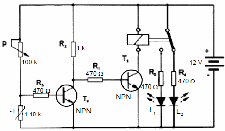
the stress on the environment when it’s hot NTC temperature sensitive circuit is reduced. T1 transmission segment T2 switches. The relay contacts will change position. If the environment is cold, the falling NTC voltage increases. Transmission T1, T2 is the sector.
Flasher circuit humidity sensor
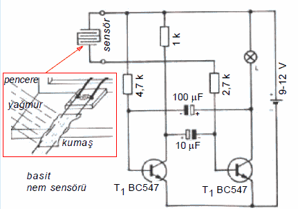
Humidity sensor no water when it comes to the passage of current in the circuit, and this transistor T2 allows to receive the flow of beyzi. Beyzi T2 to the flow of multivibrators (flip-flop) circuits of the start of the study and provides the lamp flashes.
LDR with a transistor and a light-sensitive circuit
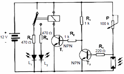
the light-sensitive circuit when the ambient light in the stress on the LDR is reduced. T1 transmission segment T2 switches. The relay contacts will change position. Falling on the LDR increases the voltage when the environment is dark. Transmission T1, T2 is the sector.
Simple circuit electronic organ
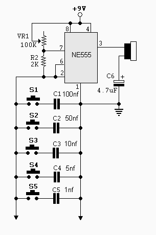
Circuit made with ne555 timer 2 and # 1 PIN is connected between produce different tones when a button is pressed. Buttons 5 buttons in tone of voice connected capacitors have a capacitor with the same port shape determines the schema and you can increase as much as you want.
Capacitor values specified in the schema, but you can change the capacitor value can be used until you find the tone you want. 1w 8ohm 0.5 W speaker output on Pins 3 can be used.
A long time delayed turn-off timer
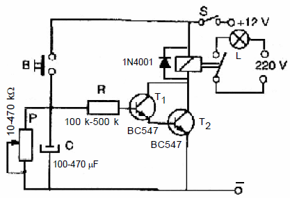
When B is pressed in the given circuit, the capacitor (C)$. We take our hands off the button, the flow of electric charge through a resistance R C in excess of accumulated triggers the transistors T1 and T2. Transistor T2 relay the message of my last runs. After a while, that would be over in the plate capacitor electrical load transistor goes into the cut, the relay returns to the first position and the lamp goes out.
The value of the resistor in the circuit of transistor T1 that connects to beyzi a very small current draws because the white tip is too large. In this way, the capacitor is discharged in a very long time.
Circuit running in the dark
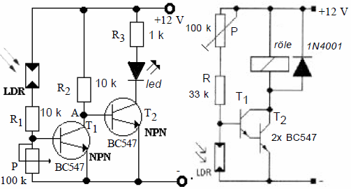
LDR increases the resistance of the circuit environment is dark. The increase in resistance causes a rise in voltage that occurs on this element. The transistors T1 and T2 are the tensions in the transmission of falling LDR puts.
Transistors relay the message of my last runs. LDR of the environment in the light resistance decreases. The tension on it is reduced. Transistor goes into the cut. The degree of the circuit with the pot’s sensitivity to light can be changed.
A long time delayed turn-on time relay
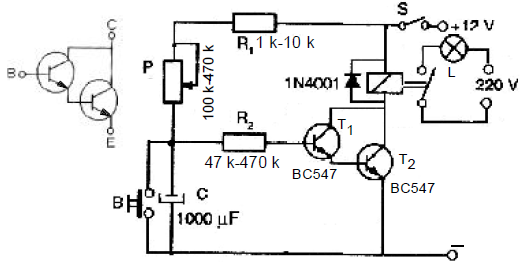
As shown in the diagram connecting a row of transistors, the more powerful,precise and high-gain transistors can be made.
Given the turn-in time switch relay circuit is closed when the front Type S, R and P C begins to charge through current flow. When you get to a certain level, the transistor T1 of the voltage C switches to transmission. At T1, T2 and the relay switches to transmission after the transmission operates. Because B would be empty if C is pressed, the circuit returns to the beginning. So, for a while to the buyer it will not work. After a certain time has passed it starts working again.
555 low power DC – AC Converter circuit
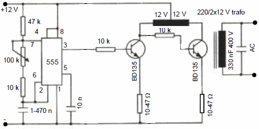
DC-AC Converter circuit 555 produces a square wave. 3 integrated transmission and puts the transistor into the cut end that is received from the square wave continuously. The conduction of the transistor of the variable flow passage 12 V transformer windings to be cut starts.
Variable currents passing through the primary windings of the transformer creates a magnetic field variable.
Very thin cross-section windings the secondary windings of primers in variable magnetic field generates a high voltage. the Note: for experimental purposes the circuit power is low.
Standing motor circuit with audio work for a while
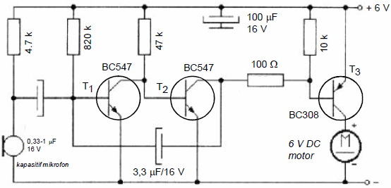
In the circuit, the transistors T1 and T2 are the transmission of audio from the microphone puts. Sour is taking over the white tip of the T2 transistor T3 message. FROM t1 to T2, capacitor a recent feedback, allows the engine to run for a while even after the sound is interrupted. Raised systolic and diastolic capacitor the value of the flour, the engine operating time is extended.
Astable multivibrator simple ultrasound transmitter circuit
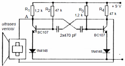
More than 20 kHz into a signal with a frequency of the ultrasonic waves in the sense of ultrasonic waves ultrasound call. Working with a signal of 36 kHz or 40 Khz frequency ultrasound the use of common circuits. Physical obstructions ultrasonic signals (even though it is transparent () cannot go.
For this reason, the ultrasonic system running under any obstacle between the transmitter and receiver
it should not be. The operating frequency of ultrasonic transducers that are used in practice 35-
39 kHz. Using ultrasonic sound to any receiver it is possible to control within 25-30 yards.
a simple ultrasound transmitter astable multivibrators Lu: the transistors in the circuit given in Figure 5.6 as the cut point in the order of transmission generates a signal in the form of a triangle. Thanks to the variable voltage that occurs in a point, the transmitter emits ultrasound at a certain frequency. The spread of the frequency value the circuit can be adjusted by changing the value of R2 or R3 ultrase you.
Optocoupler remote control circuit
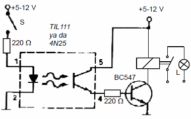
Advanced electronic circuits optocouplers (TV, PLC equipment, computer, etc.) are widely used. The advantage of these elements is to isolate two separate circuits from each other electrically. Namely, control circuit, power circuit is not affected by any. The electrical power is converted into light of changes that arise in the control circuit which controls the light sensor and the circuit element.
S when the switch is closed, the diode emits infrared beam. These rays photo-transistor. My last message by triggering the relay with bc547 ensures the operation of the phototransistor.
The photo transistor Infrared receiver circuit
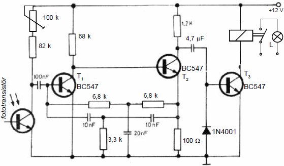
The circuit is designed so that will not be affected by daylight. So, the capacitor and the resistive circuit can detect the infrared rays with a frequency of only 2.7 kHz filters. 2,7 kHz transmitter to operate the relay from the circuit at the output rays should be sent. 2,7 kHz infrared transmitter to run the circuit a simple circuit is sufficient.
2,7 kHz transmitter, square wave shaped beam of the photo-detected by the transistor.
The transmission of the transmitter frequency with the same value continuously cutting fototransistorun collector consists of a square wave. These square waves rectified by a diode and 4.7 MF capacitor and a 1n4001. With DC current conduction of transistor T3 is inserted.
Mono Stereo Audio Signal Circuit Engaged In Pan
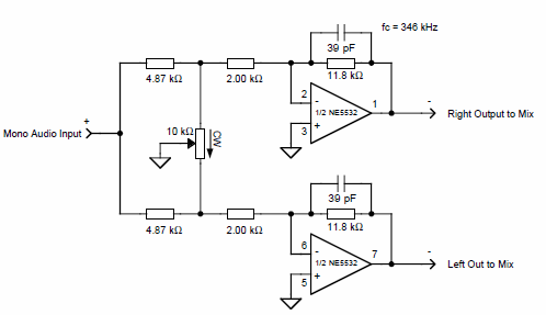
Circuit two channel mono single channel audio signal pan R-L as equally balancing circuit ne5532 op amp 10K pot that is being done with the crashes.
Fluorescent lamp inverter Converter circuit
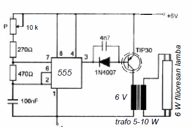
A fluorescent lamp inverter circuit fluorescent lamp in Portable lighting devices (searchlight) are used. The circuit consists of a square wave that is used in 3 of the 555 at the end. It is possible to adjust the frequency of the square wave with the pot.
555 transistor connected to the output of the primaries of the transformers continuously variable transmission and refrigerated as cutting currents to pass from causes. The currents in the primary windings to the secondary windings of the transformer from the last variable high-value leads to the formation of the angle. Secondary high-value AC fluorescent lamp burns
Photo transistor light-sensitive circuit
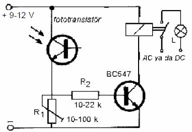
The circuit photo-transistor bc547 came to light when transmitting through e of the transistor to the conduction puts this element. The message when I have BC547, relay and pull the lamp lit. When light from the photo transistor E is interrupted, the relay reverts back to its original state. The operation of the circuit with R1 trimmer to the desired value of the light intensity can be adjusted. Obviously, the given circuit is working as sensitive to light. This circuit is only sensitive to infrared radiation of dark transparent plastic with the lens portion phototransistor if we want to be we need to shut down. When we do it, phototransistor detects infrared rays emitted by the diode transmitters only.
For example, let’s think about what we should do to set the alarm in a room. While this process is being performed mini infrared transmitter circuit a diode is mounted on one side of the room. This is placed in the circuit in Figure 3.22 to the opposite wall of the transmitter. phototransistor as soon as it enters a body from the infrared rays between the two circuits are cut off. phototransistor bc547 transistor to stick to this cutting leads. Changes the position of the contacts of the relay BC547 outgoing cutting, and burning the lamp goes out.
LDR and thyristor circuit running in the dark
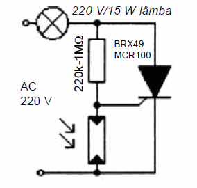
LDR and thyristor circuit running in the dark: dark ambient increases the resistance of the given circuit LDR, and the tension grows from falling over. The lamp driving voltage that occurs on the LDR thyristor runs. You see LDR media fade resistance is reduced. A thyristor conduction that occurs on the LDR shall not exceed the lesser of tension.
Electronic Circuit Diagrams Part-1
Published: 2016/04/23 Tags: simple circuit projects
H-Bridge DC motor driver circuit with IR2101
Hi friends, DC motor control I’m doing a study on. As part of this study, a DC motor H-Bridge I need to drive.
Bread on the board, IR2101 an H Bridge consisting of MOSFETs IRFZ44N and I built it. But the mosfet heatsink on the MOSFETs a 3-4 because it is not burned. interruption also on the Board. So I said I’ll make a card. good was in it. 🙂 Or quite a few with the MOSFET I was getting bored. As I said, I used the ir2101 MOSFET driver. Hin and Lin channels can be controlled independently. As a IRFZ44N Mosfet.
Elektronische Schaltpläne-Teil-2
Die meisten Kommentare werden gemeinsam mit viel verschiedene elektronische Schaltpläne einfache Struktur kann leicht umgesetzt werden mit weniger material an Bord ist die platine mit dem Sie Experimentieren können und gezüchtet