Many phones use a DTMF receiver is integrated . The majority of them are manufactured by companies that Motorola MT8870 is integrated . There are 18 pieces on this integrated pin . However, this is not integrated within the phones alone , can also be used in various applications . However, how to integrate the various projects that are used and it is not necessary to yield engineers and technicians felt the need to integrate these are tested separately .
This integrated laboratory and communications-related saves a lot of time in various manufacturing industries . A simple scheme is given for integrated DTMF here . This integrated DIP -18 with sheath structure that can be easily fitted on the PCB for a breadboard or can be easily installed on the circuit .
For optimum operation of telephone equipment , the DTMF receiver 40ms’ for more than a couple of tone and should be designed to recognize . However, remote controls , radio frequency , etc. working with or providing wireless communication applications . applications , creating a negative impact on the tone of the noise causes . Thus activated , additional strength and duration of the tone can be changed by adding a diode

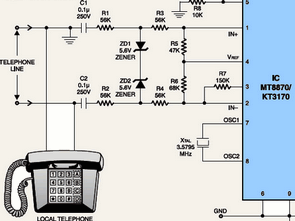
Balanced circuit is designed in line mode . Common mode noise signals a balanced differential amplifier input to prevent use . The circuit also destroyed properly (finalized) telephone line interface provides control over the mükemel . Jump to protection resistor divider and zener diode ( ZD1 , ZD2 ) can be added . These resistors and diodes, current limiting will occur on the line provides a temporary absorption of energy .
Pressing any key on the keypad of the phone when connected via R15 to the output of the std MT8870 integrates gives LED5 light . This IC is connected to pins 16 and 17 depending upon the values of resistors and capacitors will remain at a high level for a while .
Shown within the dotted lines of the material contained in the box , the time setting is used for circuit protection . LED1 connected to pins 11 and 14 of the IC … LED4 LEDs , resistors R11 through R14, respectively … are active . So the key pressed on the telephone keypad tones of the binary system is shown on the LEDs after conversion . LED1 lowest ( LSB) , LED4 highest ( MSB) bit represents .
For example, did you press the 5 key on the keypad , then to give light LED1 and LED3 ( 0101) . So for each number corresponding LEDs will light when pressed . Thus, IC, pressing the keys on the phone keypad decimal values will be read as a binary value .
MT8870 DTMF Receiver with Integrated KT3170 or the circuit for testing the following ways :
-
1) Even a parallel phone and connect the circuit .
2) Open switch S1 .
3) Now for the * key to generate tons of press .
4) Then, press decimal .
5) Compare this with what you see in the picture table .
6) If you ‘re seeing right of the decimal figures LED4 with LED1 MT8870 DTMF is correct.

Tables A, B, C and D letters you see. They are used for a special synchronizing on a regular phone because you can not see this button. For the 5th IC pin pull-down switch S2 is made. A, B, C and D tones S2 corresponding to the character button is turned off may be formed.
Published: 2012/06/12 Tags: analog circuits projects
Audio Spectrum Analyzer dsPIC30F6012 MCP6022
A Digital, real-time Audio Spectrum analyzer circuit for audio devices is presented in this project. This circuit aims to professionals or hobbyists who would like to embed it in an audio device or use it as a stand-alone unit. The Digital, real-time Audio Frequency Spectrum Analyzer can display the distribution of the audio signal energy to 20 specific frequency bands, using DSP technology. It uses fast Fourier transform (FFT) in order to monitor the entire audio signal band in real time. The obtained Fourier transform results are being processed by means of a bank of 20 parallel frequency filters and are being displayed in 20 bars on a simple 20 x 20 LED display. The unit supports four display-modes.