Speed Meter Circuit consists of four parts. These Supply solid floor Sensor sensor, microcontroller and microcontroller solid hexadecimal numbers we obtained from the 7-segment display technology with time code converter solid. Program Keil µVision3 AT89C51 microcontroller.
Supply DC 12V working with solids. However, by 7805 we have achieved solid display technology and microcontroller is supplied with 5V regulated. 12V opam the feeds OPAMPs from sensors to information received by the comparator works as and with the potentiometer we determine the reference voltage sensors have achieved with voltage compare output 0-12’re getting 12V to microcontroller directly would not go zener 5.1V a fix and this information logic 5V and 0V used it as we are .
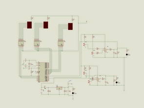
AT89C51 Speed Meter Schematic

AT89C51 LED Display Speed Meter Circuit keil source code and proteus isis simulation schematic files: author: Serdal ARSLAN
Password: 320volt.com
Published: 2008/10/07 Tags: 8051 example, avr project, keil example, microcontroller projects
Simple C++ Sample Program Codes
Prepared by the C + + programming language Simple examples include a list of contents of the file and the code of labor Thanks to the People