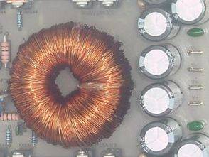
1400w 12v DC to DC converter circuit dc voltage converter circuit as symmetrical +-70V dc is turning sg3525 SMPS PWM control IC is used on the floor. In practice, the output transformer used optionally divided into two parts to meet more precisely 1400w power single core can also be used if nüvebulun. Primary and secondary windings of the wire used in the parallel connection used to be very thick.
Primary (which took part MOSFETs) 2 × 6 round wire secondary output section 5x1mm 6x1mm 2 × 24 round is hemmed in by a wire diagram, pcb winding outside the core have on the picture.


1400w DCDC
FILE DOWNLOAD LINK LIST (in TXT format): LINKS-19607.zip
Published: 2012/08/29 Tags: dc dc converter circuit, power electronic projects, sg3525 circuit
Class D amplifier Circuit 900w IR2110
Class D amplifiers are used specifically for bass thanks to the study of very small size high power switching circuit can be used to değier 22UH iE33 coil may be wound on a core (other circuit 50uh). 900W Class D amplifier circuit design has very nearly the same for the second one on the other in the IR2110 IR2010 schematics and PCB drawings of both components have been used.
I have to deal with an intermediate class d amp for the job when iE33 material is found in the market interest me, but this is difficult to test the higher powers
DC-DC-Wandlerschaltung 1400W SG3525
1400w 12v DC zu DC Konverterschaltung DC Spannungswandlerschaltung als symmetrisches + -70V DC dreht sg3525 SMPS PWM Steuer-IC wird auf dem Boden verwendet. In der Praxis kann der Ausgangstransformator, der wahlweise in zwei Teile geteilt wird, um genauer zu treffen 1400w Power Single-Core kann auch verwendet werden, wenn nüvebulun. Primär- und Sekundärwicklungen des in der Parallelschaltung verwendeten Drahtes waren früher sehr dick.
Primary (die MOSFETs teilgenommen hat) 2 × 6 Runddraht sekundären Ausgang Abschnitt 5x1mm 6x1mm 2 × 24 Runde wird durch ein Draht-Diagramm, PWB Wicklung außerhalb des Kerns haben auf dem Bild gesäumt.
Please 🙏 pdf format send to my mail last request so I can directly print
No PDF file. Copying PCB from image. Sprint layout PCB desing program.
https://320volt.com/en/using-sprint-layout-6-pcb-program/
43:01 Re drawing a PCB using scanned copies. Copying PCB from image