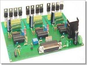
CNC-3AX board from the computer’s parallel port. Used to control 3 unipolar stepper motors (6 wires). 3 Axis Parallel port CNC control Circuit L297 stepper motor control IC is built on the output of the IC 7409 gate IC used IRLZ14 (12 pieces) MOSFETs are driven. Computer connection is provided via parallel port. It is recommended to connect all transistors to the heatsink using an insulator according to the power drawn.
For control, you can use Cnfraise, Kellycam, Cncpro, Winpcnc, Desknc programs that you know with parallel port support. There are pcb, schematic files in pdf format, and also source protel 98 files (.sch, .pcb)
Note: In the cnc3axdoc.pdf file, information about the circuit is given, motor connection, cooler, etc. “Adjusting the density circulating in the spirals of the engines,” in google translate translation in the potency settings,
potentiometers. The setting is correct when the engine is “whistling”.” I guess. For your information, it is mentioned that it is adjusted to make a slight noise when the engines are not running at idle.
3 Axis PC LPT Stepper Motor Control Board

3 axis LPT CNC schematic

In the final document is a list of board components CNC3AX. Start with soldering the smallest components, resistors, diodes, then capacitors and connectors. Place the IC on media (or tulip lyre) in order to replace them in case of malfunction. Weld then 12 transistors. Depending on the engines used will require changing the reference of these transistors (MOSFET).
If you use more than two engines amps per phase, it will put the transistors on a radiator has high dissipation. Do not forget to insert between the radiator and the transistors to an insulation kit avoid short circuits. Use a heater on the voltage regulator 7805. Without the card cooler function correctly. The power of the card must be done with a regulated power supply between 9 and 12 volts max, 500 mA. The power of the engines can be 12 volts to 40 volts. Watch out for chemical capacitors, check that the operating voltage is greater than the supply voltage motors.
Mach3 settings


3-Axis Stepper Motor CNC Control Circuit schematic pcb files alternative link :
Password: 320volt.com
Published: 2009/10/11 Tags: motor control circuit, motor driver circuit
100W Subwoofer Amplifier Circuit
M5218AP solid bass filter circuit, LM741 opamp amplfier built on symmetrical power supply + 56 – 56 volts symmetrical bass filter section 15 volt zener regulated by whether they have been power supply.
Stereo 50kω … 200hz frequency setting potentiometer VR1 is done with the 40 1k potentiometer VR3 guess the quiescent current is adjusted to be between 30 to .40 m. The recommended value for the filter capacitor in the supply circuit to be used 10000uF 63 volt transformer voltage volts AC 150W 2X40 If you want the “Sub Bass” filter section you can use a different amp circuits.
100W Bass Subwoofer Amplifier Schematic