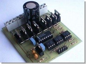
A circuit that enables the stepper motor to be controlled using the parallel port of the computer, the data inputs are made through the 6N135 opto-couples, so that the parallel lpt port is protected. Two motors can be controlled, it can provide 5 amps per channel. There is a total of 10 amps power. The driver mosfets are 8 pieces of IRF540 control IC CD4094B
This circuit makes it possible to control eight power switches that can handle loads of several amps with supply voltages up to 50V via the parallel port of the PC. The circuit is optically isolated from the PC for safety reasons.
A classic application is to drive a pair of unipolar stepper motors, but is also suitable for controlling eight light bulbs or eight DC motors.
The mechanism adopted in connection to PC allows these circuits to be connected to a single parallel port of up to six for a total of 12 stepper motors or 48 bulbs.
The short sample software that I have provided both the executable and source code of allows you to test the operation of a pair of stepper motors in a Windows environment. They are based on the VVIO project libraries. Note that to connect this circuit to the parallel port, you must connect a suitable cable or create a suitable printed circuit board.
Unipolar Stepper Motor Driver Schematic

The circuit is designed to drive loads that require a continuous supply voltage of 14 to 50 V (it is also possible to use lower supply voltages with some precautions) and a maximum current of 5A per channel. Total continuous 10A. I recommend not using stabilized power supplies: just a simple transformer, a diode bridge and an electrolytic capacitor of sufficient capacity (one thousand uF per amp) or a 12 or 24V battery. Note that the current absorption and supply voltage are quite high so minimal care is required when handling the circuit. In particular, do not connect or disconnect the circuit from the power supply while voltage is present,
The MOSFET determines the supply voltage and maximum current that can be managed by the circuit. Required specifications primarily type (N channel, TO220)
The supply voltage of the circuit should be +3 volts higher than the threshold voltage of the MOSFET. If the supply voltage is up to 8V or less, you need:
Use “logic level” MOS (e.g. BUK553) characterized by a lower switching voltage
Change the values of R8 and R9 (for example at 5V) to fix the power supply of the CD4094B chip to a voltage compatible with the operation of the MOS and the chip itself
Decrease the values of R2, R4 and R6 to keep the current unchanged (eg 2k2 for 5V power supply)
Note that the LM317HV requires an input voltage of at least 2V (in this particular case), higher than the output voltage. At the limit (but just at the limit…) you can eliminate this IC, replace it with a jumper between Vdd and Vp, and add a 4.7V / 1W “volate” zener between Vdd and Vss. In this configuration, care must be taken to ensure that the supply voltage does not exceed 10V.
The maximum value of Vcc depends on the MOS (it is normal to find hundreds of volts…) but it also depends on other components, especially the voltage regulator and electrolytic capacitors C1 and C5: this actually limits the use of Vcc. 50V circuit.
The MOSFET also determines the maximum current that can be supplied to the load. In reality, the problem isn’t due to the component’s maximum current (it’s easy to find MOSs of tens of A) the maximum power that can be managed without a heatsink: it is necessary to select components with low enough Rds-on.
For example, the IRF540, a typical MOS in a 30A/100V TO220 package, has the following features:
63 °C/W thermal resistance without heatsink
A conductor resistance of less than 0.077 ohms (Rds-on)
This means that the maximum dissipation at 50°C is about 2W, equal to the maximum continuous current of about 5A. This value obviously depends on the MOS parameters, especially Rds-on.
Another critical element when using high inductive loads are the eight diodes placed in parallel with the load: they protect the MOSFET from overvoltage tripping. They should have the following features:
The choice of component can cause some difficulties, but the biggest problem is finding it on the market: I found a package of unspecified diodes to replace power supplies at a flea market… A piece of advice: a very common 1N4007 is better (but very slow) this is nothing.
C5. It would be better to use a low ESR capacitor, but a “regular” electrolytic is also fine if you don’t have one. The capacity should be high enough, but not critical; On the other hand, operating voltage (if it’s low there’s a risk of blowing up, making a big explosion) and physical size (a little bit of the printed circuit is sacrificed…) are important.

Source: vincenzov.net Unipolar Stepper Motor Driver Circuit schematic PCB files alternative link:


CCS C PWM Calculator
CCS C PWM Calculator Lately, I have been doing a lot of maths on my own because of my IR Obstacle detector design. Noticed a lot of people asking for help on configuring PWM using CCS C.
CCS C PWM Winzard